

You are here
Back to topTips For Remotely Measuring Ripple
In the power supply system, the converters output voltage ripple and noise usually affect the stability of the system, so the system designer will be highly concerned about how to correctly evaluate the ripple voltage value in some sensitive circuit. The common measurement method is to use a voltage probe to measure converter output point with close range, but the components of the modern electronic system are becoming smaller and smaller, and it is often hard to measure the object directly by using the voltage probe, so it is necessary to measure the test point with a long wire from some distance. Due to this method may be subject to random noise interference introduced by the external pull in, and the measurement value cannot be ensured, and the converter ripple value to be measured could not be correctly. Therefore, this following will show how to accurately evaluate the converter ripple and noise test method when long-distance measurement is must be required
1. Introduction
1.1 Ripple and Noise
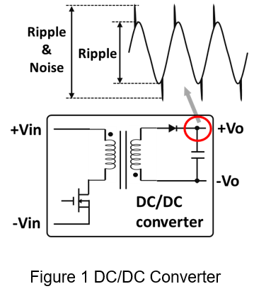
Ripple generally refers to the amount of change in AC voltage that occurs on a DC power converter. The phenomenon is mainly generated by the converter in the process of electromagnetic rectification conversion and cannot be completely eliminated. The example of a DC/DC converter as shown in Figure 1, it can be seen that the converter sometimes contains output ripple voltage and noise because the parasitic properties of the material inside the converter will cause voltage noise during the switching process, and lead to the result of we measure at the output capacitor to produce a ripple voltage containing noise component.
1.2 Measurement Method
Figure 2 shows a long-ground measurement method used in general measurement. Because the length of the ground wire is long, it is equivalent to increasing the parasitic inductance of the measurement loop. Therefore, when measuring the ripple voltage, it is easy to cause noise in the waveform of the voltage.
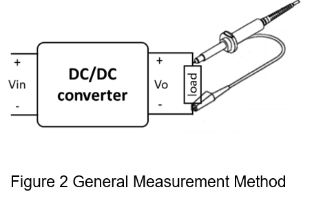
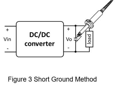
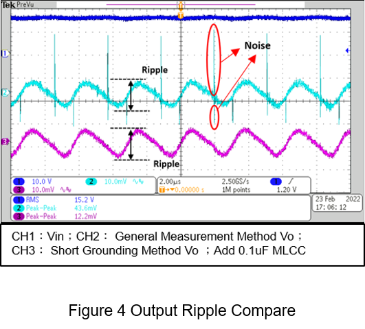
Figure 3 shows a common short-ground ripple measurement method. The probe ground terminal should use the shortest distance to measure signal in order to avoid measuring noise. The measurement point is changed from the resistance-load to the capacitor-load, and the purpose of this capacitor is to suppress high-frequency noise, and the capacitance value is usually not too high, mostly between 0.1uF and 1uF. The CH2 and CH3 in Figure 4 are the ripple difference plots measured by the general measurement and short grounding methods, respectively, and the measurement method using short-ground can eliminate noise effectively and measure ripple voltage accurately.
1.3 Long-Distance Measurement
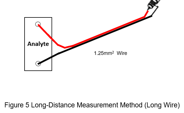
When the probe cannot directly measure the ripple voltage of the DUT, the most common method is to use a long wire to extend the two ends of the DUT, as shown in Figure 5. This method can be used in the measurement of general voltage signals. However, when used to measure the ripple voltage, it is easy to be interfered with the parasitic stray inductance on the long lead and impedance matching, resulting in voltage waveform variation. The measurement result is not a real converter characteristic.
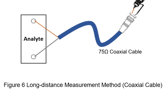
In order to reduce the noise interference of the line during long-distance measurement, the coaxial cable can be used for long-distance measurement, the structure of the coaxial cable has a good shielding of electromagnetic interference, which can greatly reduce the parasitic noise on the conduction path. While the transmission of a long distance has the least signal attenuation, and can retain the signal to the greatest extent, as shown in Figure 6, it should be noted that the shorter the connection path from the coaxial cable outlet end to the DUT can easy to reduce interference.
2. Actual Measurements
Comparing the differences by using two wire stocks to measure the output ripple voltage over a long distance through the same DC/DC converter. The converter specifications are shown in Table 1, and a 0.1uF MLCC is connected to its output, and a 1x voltage probe is used to measure the results of short-distance grounding as a control group; the extension cable used is a 75Ω coaxial cable and a 1.25mm2 long straight wire, and the length is 1.5-meter and 3.0-meter respectively; the oscilloscope input impedance is set to 1 MΩ, and the bandwidth is set to 20MHz.
| DC/DC Converter | |
| Input voltage | 15Vdc |
| Output | 5 Vdc / 0.5A |
| Operating frequency | 330kHz |
| Ripple & noise | 20mVp-p (max) |
2.1 Long Wire
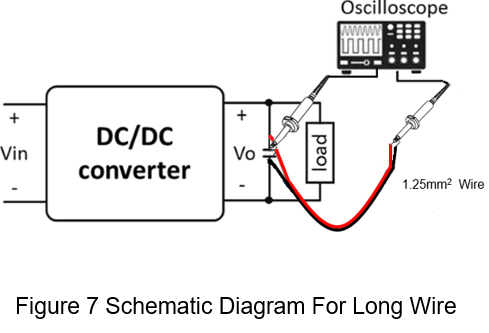
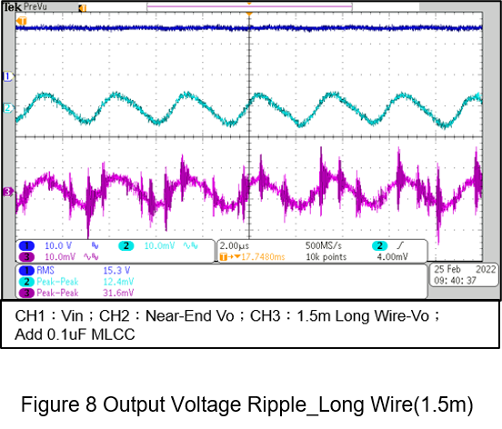
Figure 7 shows a schematic diagram of a long wire group test, The capacitor (near end) of the converter load and the ripple voltage measured by the extension of the long lead are measured by the method. CH2 in Figure 8 is the near-end ripple voltage, and CH3 is the ripple voltage measured using a 1.5-meter long wire. It can be seen that the ripple waveform measured using the long wire is interfered in Figure 8, affecting the user's analysis of the converter's output voltage ripple, and the overall output voltage ripple is about 31.6mVp-p.
2.2 Coaxial Cable
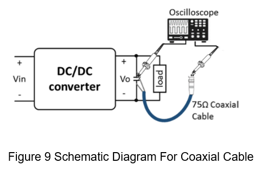
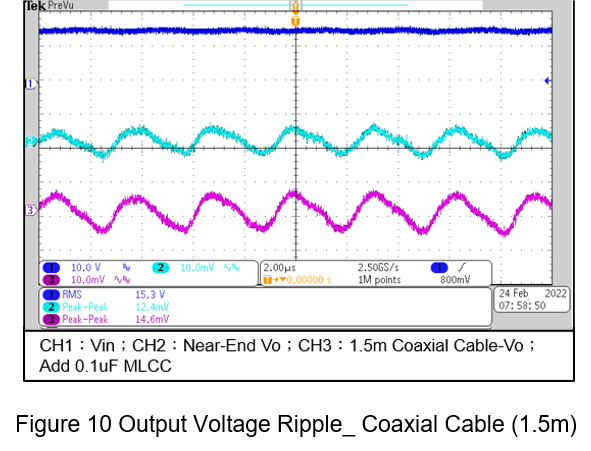
Figure 9 shows a schematic of a coaxial cable wiring, using a 1.5-meter coaxial cable instead of a long wire, and comparing it to the ripple voltage measured by the capacitor (near-end) at the converter output. Figure 10 shows the output voltage ripple measurement results, where CH2 is the near-end ripple voltage, CH3 is the ripple voltage measured by the use of 1.5-meter of coaxial cable, from the Figure 10 can be seen that the waveform obtained by the coaxial cable is similar to the near-end waveform, relative to the long-distance ripple voltage measurement method is more suitable for long-distance ripple voltage measurement, the overall output voltage ripple is about 15.6mVp-p.
2.3 Effect of Distance on Long-Distance Measurement Ripple Voltage
When measuring the ripple voltage over a long distance, the length of the extended wire will affect the waveform of the output ripple voltage, and under other conditions, the comparison of the impact of the cable length on the output voltage ripple when the length of the wire is 1.5-meter and 3.0-meter, respectively.
Figure 11 shows the ripple voltage of the remote output of the long wire, CH2 and CH3 are 1.5-meter and 3.0-meter of long wires, respectively. It can be seen from the Figure11 that the long wire is greatly disturbed during the transmission process, and the converter output voltage ripple cannot be presented, and the interference situation will be more serious as the distance increases. As the overall ripple voltage peak of the 3.0m long wire comes to about 47.6mV, which shows the simple long wire is not suitable for measuring the ripple voltage at a long distance.
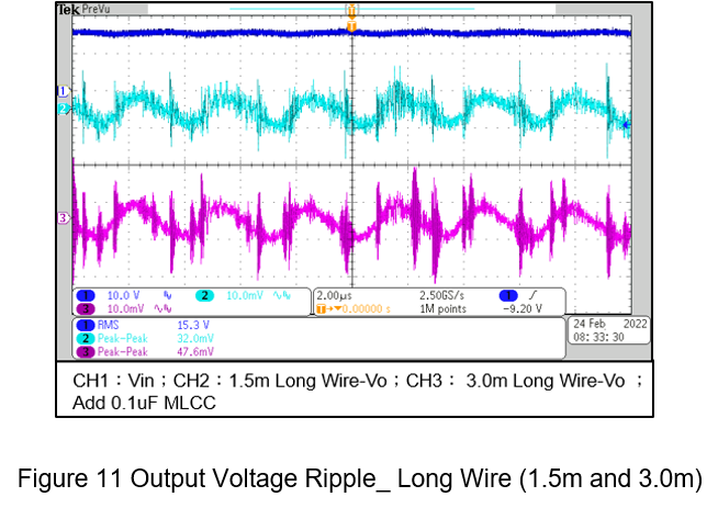
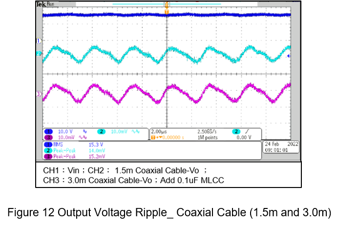
Figure 12 shows the output voltage ripple at the far end of the coaxial cable with lengths of 1.5 meters and 3.0 meters respectively. It can be seen that the coaxial cable with the increase of distance can still maintain the waveform of the near-end ripple voltage without much distortion, and the amplitude of the noise is smaller than the long wire case. The overall ripple voltage of the 3.0-meter coaxial cable is only 15.2mVp-p, which is only 1.2mV compared with the 1.5-meter coaxial cable.
3. Summary
In this paper, the effects of different wires and distances on long-distance measurement are preliminarily sorted out, and the results are listed in Table 2. Coaxial cables are relatively suitable for long-distance ripple voltage measurement cables than long wires, and can maintain the waveform completely of output voltage ripple in a certain distance, and obtain the ripple voltage through long-distance measurements when they are limited by the size of components, thereby reducing the misjudgment caused by line noise.
| Proximal | Coaxial cable | Wire | |
| Proximal | 12.4 mV | ||
| Length 1.5meter | 14.0 mV | 32.0 mV | |
| Length 3.0meter | 15.2 mV | 47.6 mV |
CTC is a professional service provider for high-end power supply modules (AC to DC Converter and DC to DC Converter) for critical applications worldwide since 30 years. Our core competence is to design and deliver products with leading technologies, competitive pricing, extremely flexible lead-time, global technical service and high-quality manufacturing (Made In Taiwan).
CTC is the only corporation certificated with ISO-9001, IATF-16949, ISO22613(IRIS), and ESD/ANSI-2020. We can 100% ensure not only the product, but also our workflow and service to match quality management system for every high-end application from the very beginning. From design to manufacturing and technical support, every single detail is operated under highest standard.