

You are here
Back to topReverse Polarity Protection Methods
Most power converters cannot withstand accidental reversal of input voltage polarity. If not protected immediately, the components of PCBs may be burned due to high short-circuit current. Therefore, reverse polarity of the input voltage is a problem in many applications, including auxiliary batteries in electric vehicles and mobile equipment. In this article, we’ll briefly examine some simple methods for protecting power converters from reverse polarity and protecting the overall system.
Introduction
Operator safety is crucial when operating heavy equipment in diverse industrial settings, such as boiler control systems and electric hydraulic pumps. It is critical for users to recognize the signs of reverse polarity and understand its potential impact on power converters, which can help protect the overall system from external factors. Reverse polarity in power converters can be caused by several issues, the most common being improper battery installation, negative transient voltages, component misplacement or orientation, and wiring errors during assembly.
Observing the signs of reverse polarity in advance can help avoid electrical hazards and aid in developing protective measures. Some symptoms of reverse polarity problems include:
- Unusual Operation: Electronic equipment may exhibit unstable performance, such as making abnormal noises, operating intermittently, or even failing completely.
- Overheating Components: Reverse polarity can cause a large short-circuit current along an unintended path, leading to overheating of components. This can burn sensitive components such as transistors, potentially causing permanent damage.
- Sparks: During long-term operation of heavy industrial installations beyond their originally intended lifespan, a large negative transient voltage may appear at the power supply end. At this time, micro sparks might pop up around the equipment, increasing the likelihood of fire or explosion.
Reverse Polarity Protection Circuit
The three circuits described below is often useful to provide protection against accidental reverse polarity for power converter. This brief description will explore three simple methods for protection.
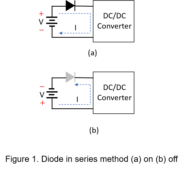
1. Diodes in Series
The method is typically used for low-current applications. The strengths of the circuit are including simple architecture, fast blocking and lower cost, but as the input current increases, the power consumption will be greater and the more heat will be accumulated, so enhancing heat management to conduct heat is required. If the power supply polarity is connected correctly, the input current will flow into the power converter, as shown in Figure 1(a); otherwise, the input voltage polarity is reversed, the diode can prevent the input current from flowing, thereby protecting the power converter, as shown in Figure 1 (b).
2. Transient Voltage Suppressor in Parallel
This type of reverse polarity protection circuit involves connecting a fuse between the circuit and the load, with a transient voltage suppressor (TVS) in parallel with the power supply. Depending on the application requirements, select the peak pulse current and reverse maximum working voltage of the TVS. The strengths of this circuit include nearly no voltage drop and low leakage current. When a reverse polarity event occurs, the current through the fuse will exceed the maximum withstand value, causing it to melt immediately. Although this structure is simple, it is important to consider that the diode and the fuse might not fail simultaneously. As a result, the power converter could be reverse biased for a short time, which must be taken into consideration.
![]()
3. MOSFET
The problems of power dissipation in resistors and voltage drop in diodes are naturally occurring. For the ultimate in low voltage drop and high current capability, replacing the diode with an N-channel FET or P-channel FET is the better choice, as shown in Figure 3. This method is similar to using diodes in series, but with the MOSFET acting as a switching element, resulting in very low power dissipation and voltage drop.
To implement this using a P-MOSFET, an N-MOSFET can also be used with slight circuit variations. Connect the input source to the drain pin, the power converter to the source pin, and connect the gate pin to ground. If the input voltage is below the maximum gate-source voltage (Vgs) of the transistor, it will be transferred to the power converter through the P-MOSFET. To avoid damage to the P-MOSFET in the case of a reverse polarity voltage higher than tolerated, a Zener diode and a limiting resistor must be added to clamp the gate-source voltage.
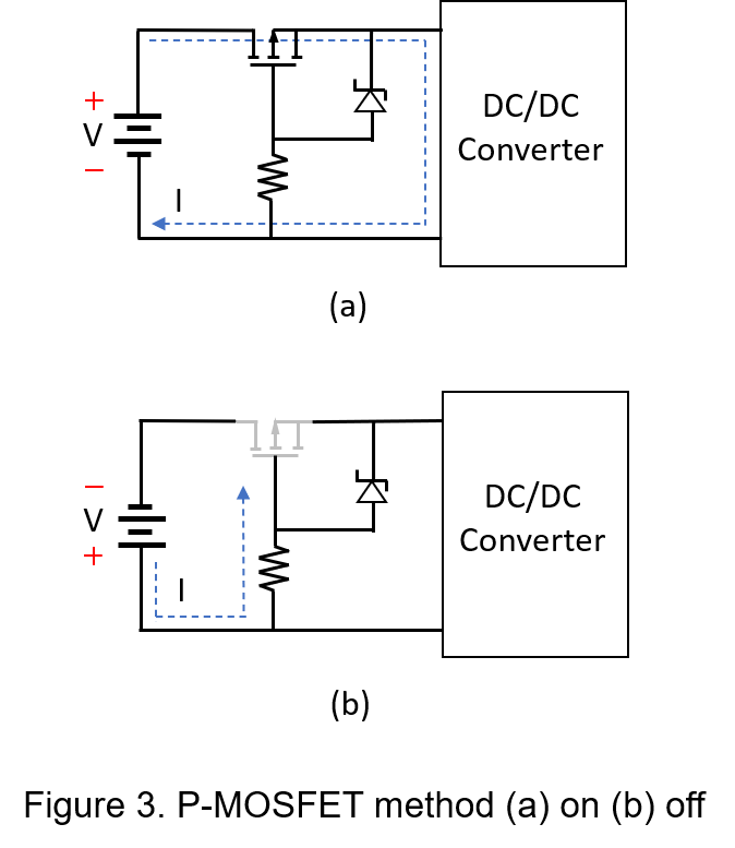
During normal positive bias operation, the body diode of the transistor is in a forward-biased state, allowing input current to flow into the power converter. During reverse polarity bias operation, the body diode of the transistor is in a reverse-biased state, causing the transistor to be in a cutoff state. To prevent high surge voltage from damaging the transistor, a current-limiting resistor and a Zener diode are added. However, the Zener diode and the current-limiting resistor will form a leakage path in a reverse polarity voltage state. Despite technical advances in efficiency, devices in standby continue to flow a significant amount of leakage current.
In design, an important consideration is the on-resistance of the P-MOSFET. The lower this resistance, the lower the voltage drop in the source-drain path. Another consideration is selecting a slightly larger current-limiting resistor, which can reduce standby current. However, if the resistance is too large, it will cause longer transistor turn-on and turn-off times and lower clamping performance.
Conclusion
This article mentions that reverse polarity protection circuits can be composed of diodes, transient voltage suppressors (TVS), or MOSFETs, each offering a different set of advantages and disadvantages. Users can choose the best protection circuit based on their input voltage, conversion efficiency, and power requirements, and then use the simplest circuit that will suffice for those needs. For example, diodes, limited by forward current and voltage drop, are not suitable for large input current situations. TVS has low leakage current features, but users should be careful about peak pulse current and fusing current. MOSFETs offer nearly no voltage drop and low transient time.
CTC is service provider for high-end power modules (DC to DC Converter and AC to DC Converter) for critical applications worldwide since 1987. We aim to be business generator and a virtual business unit. CTC is your own team with 35 years of experience for a strong business program from market research, product definition & development, supply chain management and total technical services.
CTC is the only corporation certificated with ISO-9001, IATF-16949, ISO22613(IRIS, AFNOR silver certificate), and ESD/ANSI-2020. We can 100% ensure not only the product, but also our workflow and service to match quality management system for every high-end application from the very beginning. From design to manufacturing and technical support, every single detail is operated under highest standard.