You are here
Back to topRemote Control Technology Applied in Industrial Automation
With the accelerating trend of industrial automation, converters not only require high conversion efficiency and compliance with safety regulations but also demand more control applications. Therefore, achieving technological breakthroughs during the product development phase is essential to realizing the benefits of smart manufacturing. This article describes the control architecture of remote control technology, introduces the control potential defined in the specification, and finally implements an external circuit connection for the converter to enable smart control and energy-saving functions.
Introduction
Smart production lines provide functions such as remote monitoring or testing of instruments during the manufacturing process. For example, during the testing phase of manufacturing, a microcontroller can wake up specific equipment to operate and completely shut it down after operation ends. Alternatively, for critical equipment that operates continuously for 24 hours, it can immediately halt operation in the event of a major incident.
In power converters, microcontrollers (MCUs) paired with sensors enable intelligent monitoring and management functions, such as scheduled shutdowns for air conditioners, sensor-activated streetlights, and automated billing for cash registers.
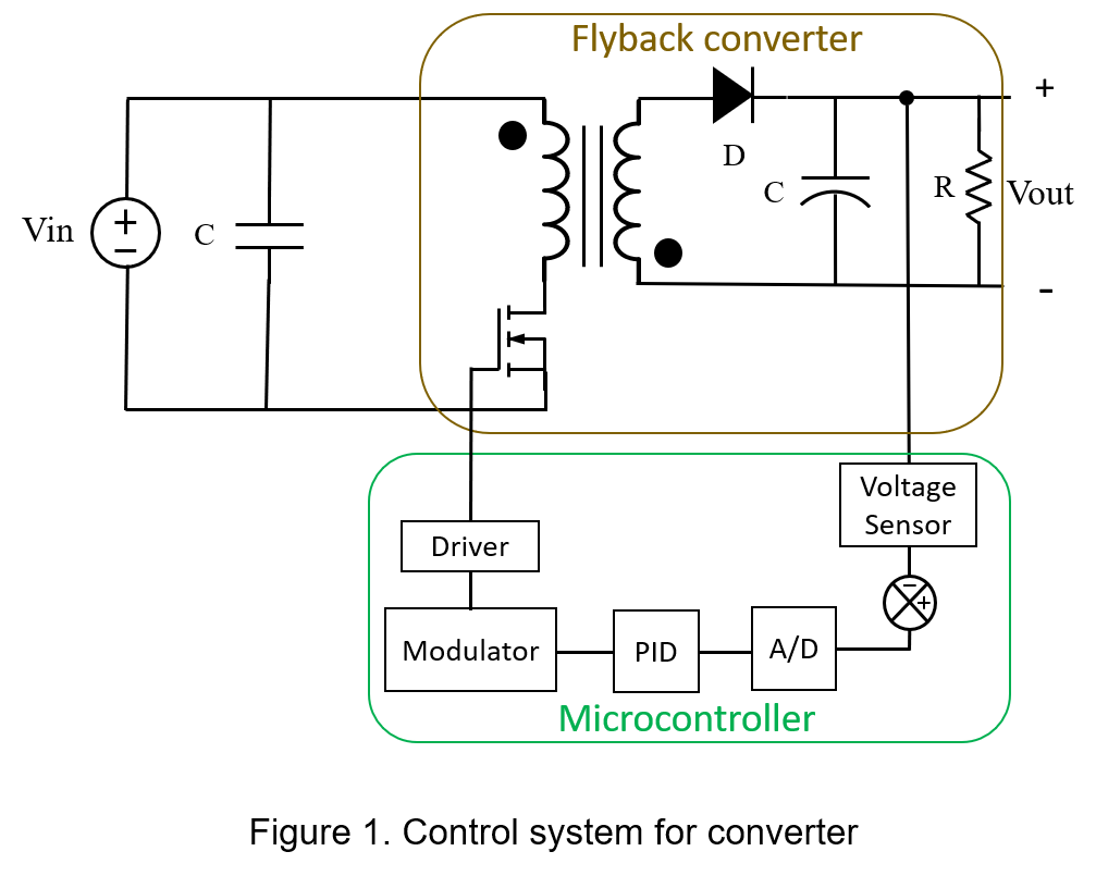
If remote control functions can quickly address issues and immediately meet user needs, energy-saving benefits can be achieved. Therefore, effective power and energy management can enhance production efficiency across industries, reduce costs, and prevent major problems such as unexpected power outages or shutdowns of critical equipment. The following will gradually introduce remote control functions and various circuit implementation methods.
Remote Control Function
For users who need to save power consumption or require timing control, power converters with remote control functions must be selected, as shown in Figure 2.
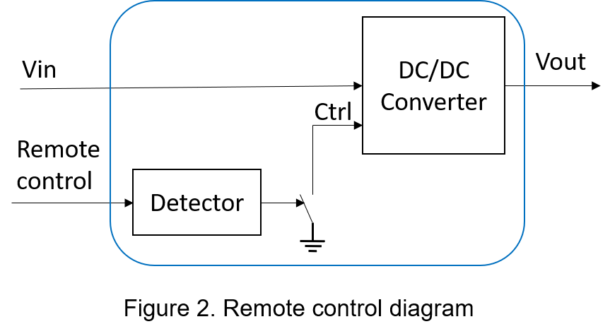
Common remote control architectures can be divided into positive logic and negative logic. Positive logic indicates that when the control signal is at a high voltage level, the converter operates normally. Negative logic indicates that when the control signal is at a low voltage level, the converter operates normally. Regardless of whether it is positive or negative logic control, when the converter stops operating and is in standby mode, the power consumption in standby is significantly lower than during normal operation. In actual system operation, the MCU remotely controls the working timing of the power converter, shutting down unnecessary high-power-consuming circuits while retaining only essential functions. In this way, energy saving and carbon reduction can be easily achieved.
Users can determine the switching method of the converter based on their specific needs. The recommended external circuits for remote control functions can be categorized into two types: short-circuit/open-circuit control signals and external drive control signals.
Table 1 extracts the logic and operating ranges of remote control from the product specification. When the control pin of the converter is open or at a voltage level of 3.5–15 Vdc, the converter operates normally. When the control pin is shorted or at a voltage level of 0–1.2 Vdc, the converter shuts down.
| Parameter | Condition | Min. | Typ. | Max. | Unit |
| Remote ON/OFF | DC-DC ON | Open or 3.5~15VDC | |||
| DC-DC OFF | Short or 0~1.2VDC | ||||
| Input current (remote off mode) | 2 | mA | |||
Commonly, two types of control methods are identified. One involves manually pressing a button switch, which forcibly disconnects or shorts the control pin to ground, as illustrated in Figure 3.
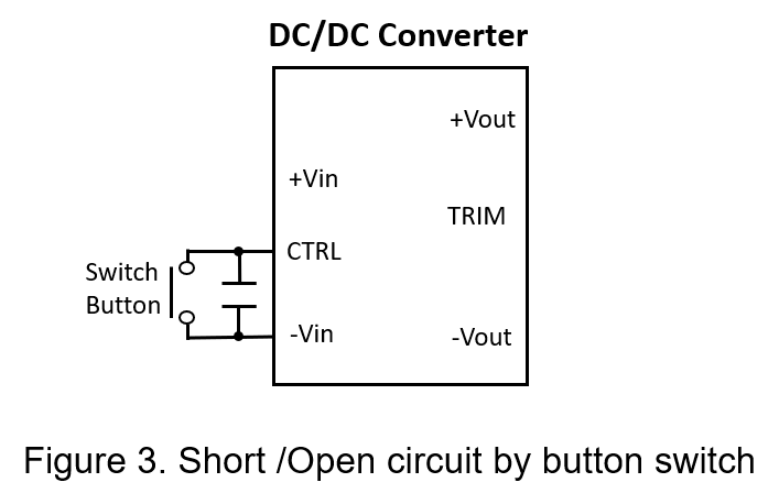
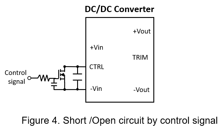
Alternatively, a digital input control signal can be used to turn the MOSFET on or off, as shown in Figure 4. When the control signal exceeds the MOS threshold voltage, the control pin shorts to ground, and the converter shuts down. Conversely, when the control signal is below the MOS threshold voltage, the control pin disconnects, and the converter operates.
Another approach uses an external reference voltage to control remote switching. For instance, as specified in Figure 5, when the external reference voltage exceeds the recommended value, the CTRL pin is set high, and the converter operates normally. When the external reference voltage is below the recommended value, the CTRL pin is set low, and the converter shuts down.
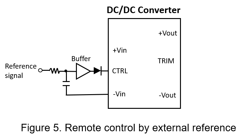
The reference voltage (Vref) value is chosen based on the operating range of input voltage and drive current for remote control specified in the product manual. In actual use, it is recommended to connect a forward-biased diode in series to prevent interference from external noise that may cause the CTRL pin to malfunction. For example, if the converter's remote control voltage range is 3.5V<VCTRL<15V, then the reference voltage minus the diode's forward bias voltage must fall within this range.
Experimental
By using control signals to turn the converter on and off, the output voltage waveform and input current were measured in both operation and standby modes. The converter tested is a wide input voltage range stabilized converter, operating at 18-75V input, with a 24V output and 15W output power. It also features remote control functionality, as detailed in Table 2.
| DC to DC Converter | 15W, 1" x 1" Package |
| Input Voltage | 48 Vdc |
| Output voltage/current | 24 Vdc / 0.625A |
| Ripple & noise | 100mVp-p (max) |
| Operation Temperature | -40~100°C |
The operational description of this positive logic converter is as follows: when the control pin voltage is within 3.5V−15Vdc or open, the converter operates normally. When the control pin voltage is within 0−1.2Vdc or shorted, the converter shuts down. The actual circuit connection is based on Figure 5. The selection of circuit components requires attention to various factors, such as choosing a filter capacitor with low equivalent series resistance (ESR) and an N-MOSFET switch with a low gate threshold voltage and high drive current.
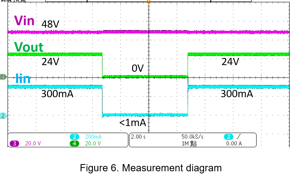
Figure 6 shows the actual measured signals, including the converter’s input voltage, output voltage, and input current signals. When the external signal is low, the N-MOSFET is off, the CTRL pin voltage rises to 5Vdc, and the converter outputs normally. Conversely, when the external control signal is high, the N-MOSFET conducts, bringing the CTRL pin voltage down to 0Vdc, causing the converter to stop outputting. The input quiescent current in this state is less than 1mA, significantly lower than the normal operating load current, leading to substantial energy savings.
Conclusion
Selecting converters with remote control features and appropriate control circuits enables low power consumption and timing control for system circuits. It is crucial to ensure that the control pin voltage complies with the logic and operating range specified in the product manual for remote control. Deviating from the specified voltage range may cause abnormal switching of the converter.
CTC is service provider for high-end power modules (DC to DC Converter and AC to DC Converter) for critical applications worldwide since 1987. We aim to be business generator and a virtual business unit. CTC is your own team with 35 years of experience for a strong business program from market research, product definition & development, supply chain management and total technical services.
CTC is the only corporation certificated with ISO-9001, IATF-16949, ISO22613(IRIS, AFNOR silver certificate), and ESD/ANSI-2020. We can 100% ensure not only the product, but also our workflow and service to match quality management system for every high-end application from the very beginning. From design to manufacturing and technical support, every single detail is operated under highest standard.

