You are here
Back to topThe Key to Advancing Power Converter Technology: Planar Transformers
As the demand for high power density increases, the packaging size of power converters is becoming progressively smaller. Traditional transformers, characterized by their large size and low efficiency, hinder the miniaturization process of isolated power converters. Today, planar transformers are gradually replacing wire-wound transformers, not only reducing the size of power converters but also significantly improving conversion efficiency. This paper explains common transformer losses, the structure of planar transformers, design considerations, and compares them with wire-wound transformers in terms of conversion efficiency, size, and system reliability.
Introduction
The operation of isolated power converters involves storing energy on the primary side and using transistor switches to interrupt the input circuit, transferring the energy stored in the transformer core to the secondary side for voltage conversion. During this process, the transformer determines most of the voltage conversion efficiency and occupies a significant portion of the converter's area, as illustrated below.
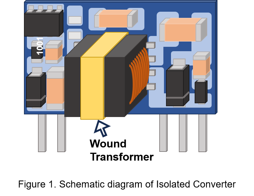
Increasing the switching frequency can reduce the transformer's size, but higher frequencies result in greater core losses (including hysteresis and eddy current losses) and copper losses (due to the skin effect), reducing conversion efficiency. In high-frequency applications, planar transformers address these losses, achieving conversion efficiencies of over 90%. Below, we discuss the common losses in transformers used in high-frequency applications.
Transformer Copper Losses and Core Losses
The iron core inside the transformer is made of magnetic material, and core loss is generated by the iron core. When power converters operate at high frequencies, magnetic materials undergo repeated magnetization, causing saturation and hysteresis losses. Copper loss refers to the DC resistance loss of the transformer winding. In high frequency applications, coils can experience skin effect, increasing resistance.
1. Core Hysteresis Curve
The hysteresis curve refers to the relationship between magnetic flux density (B) and magnetic field strength (H). This relationship is nonlinear. As the magnetic field strength increases, the magnetic flux density rises along the curve until it reaches the point Bs. At this point, even if the magnetic field strength continues to increase, the magnetic flux density tends to increase at a slower rate, a phenomenon known as magnetic saturation. Transformer saturation can result in a decrease in inductance, causing excessive current through the transformer windings and potentially damaging switching components. Therefore, transformer designs must avoid magnetic saturation.
When the magnetic field strength decreases, the curve follows a different path, returning to the point Br where the magnetic field strength equals zero. If the magnetic field strength continues to decrease, the curve reaches the point Hc, where the magnetic flux density equals zero. The hysteresis curve is shown in the diagram below.
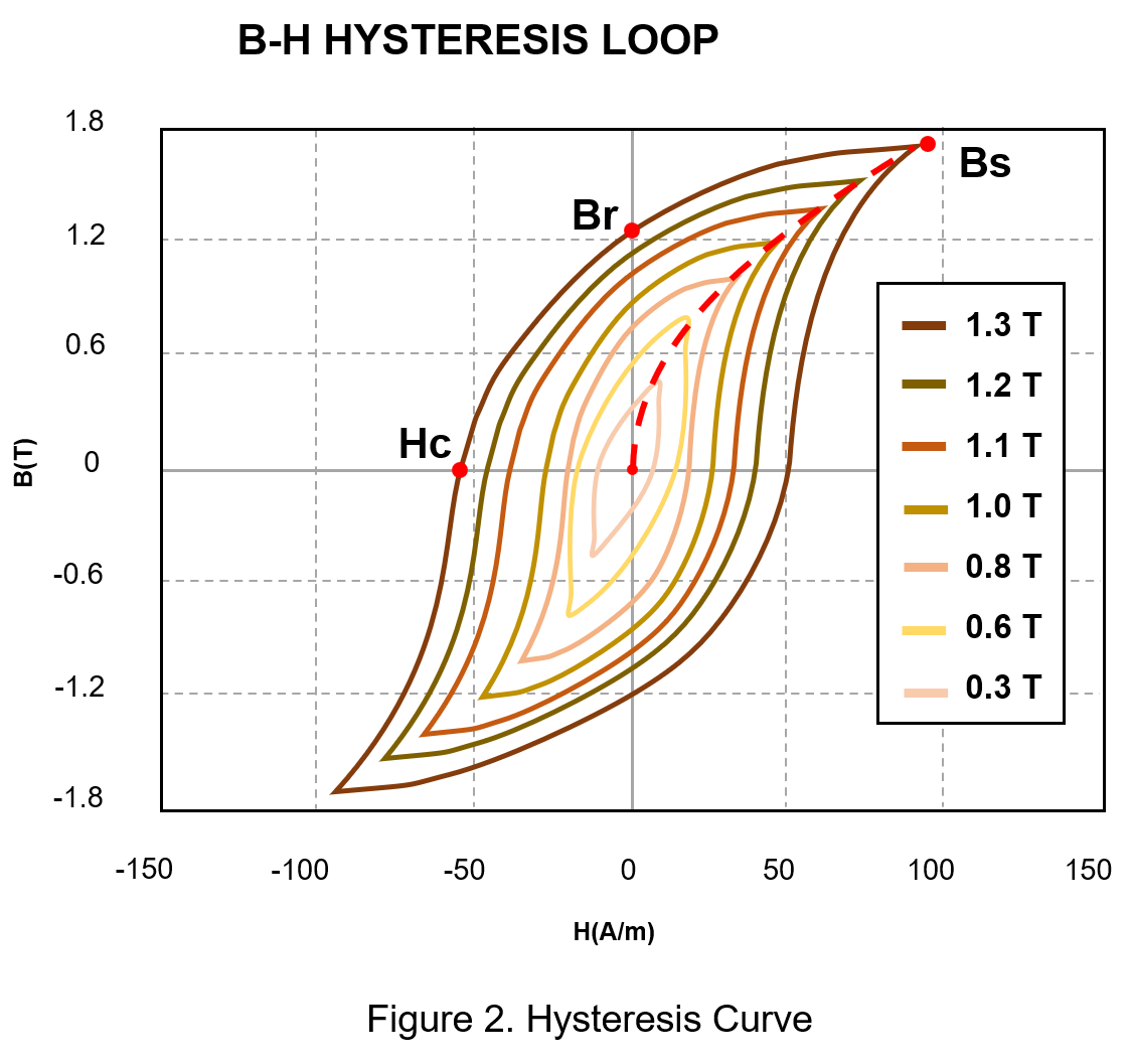
When current flows through a winding coil, the coil generates a magnetic field, causing changes in the magnetic field within the core. Under the influence of this magnetic field, the magnetic domains inside the core slowly rotate, expand, and contract. These phenomena result in internal friction among the material, generating heat, which is referred to as hysteresis loss (Ph). The area enclosed by the hysteresis loop represents the hysteresis loss; the larger the area, the greater the hysteresis loss. The formula for hysteresis loss is as follows:

Where:
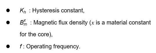
From the formula, assuming a constant magnetic flux density, the hysteresis loss is proportional to the frequency. As the frequency increases, the hysteresis loss also increases. In high-frequency operations of power converters, this leads to reduced efficiency and increased heat generation.
In contrast, planar transformer cores are made of ferrite soft magnetic materials, which effectively reduce hysteresis loss caused by high frequencies.
2. Skin Effect in Winding Coils
Transformer windings are made of enameled wire. When an alternating electromagnetic field is present in the conductor, the current tends to concentrate on the surface of the conductor. This results in higher current density on the surface of the wire and lower current density at its center, a phenomenon known as the skin effect. The illustration below depicts this effect.
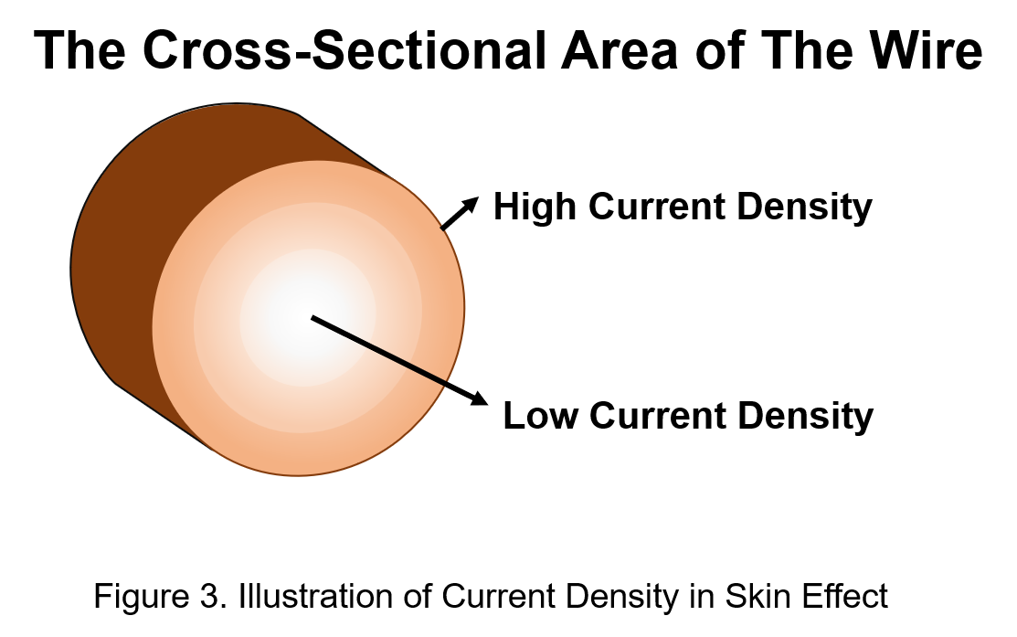
The utilization rate of the conductor's cross-sectional area decreases, leading to increased resistance and power loss, a phenomenon known as the skin effect. As the operating frequency of the power source increases, the current in the conductor becomes more concentrated on its surface, causing the resistance to rise proportionally with the frequency.
In high-power applications, traditional transformer windings require thicker coils, which may exacerbate the skin effect, resulting in higher losses and reduced conversion efficiency. In contrast, planar transformer windings use copper foil on printed circuit boards (PCBs). By increasing the thickness and width of the copper foil, planar transformers can meet high-current demands. Additionally, due to the low number of coil turns, the skin effect can be effectively ignored.
What is a Planar Transformer?
A planar transformer is a type of transformer constructed using multiple layers of PCBs. The primary difference between a planar transformer and a traditional transformer lies in the core and winding design. Planar transformers offer advantages such as high performance, high-frequency operation, and compact size, making them suitable for high-power applications in power converters.
1. Winding Design
The windings of a planar transformer use spiral traces on a PCB to replace traditional wire windings. The center of the PCB is hollowed out to accommodate the magnetic core material, which is stacked and secured with insulating tape. This structure makes planar transformers extremely thin, reducing size while achieving higher power density and efficiency. Furthermore, they offer excellent thermal management capabilities. The diagram below illustrates the structure of a planar transformer.
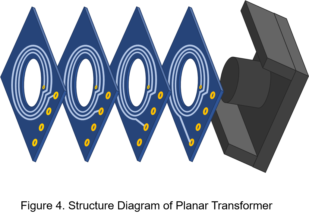
Using PCB traces for winding eliminates the risks associated with traditional transformer winding processes, such as short circuits, open circuits, and wire displacement during stacking. Additionally, interlayer insulation with thin insulating films or pads reduces the chances of conductor insulation damage and isolation voltage defects. The planar structure of planar transformers ensures tight coupling of the windings, improving high-frequency parasitic parameters and reducing DC resistance and leakage inductance.
2. Core Selection
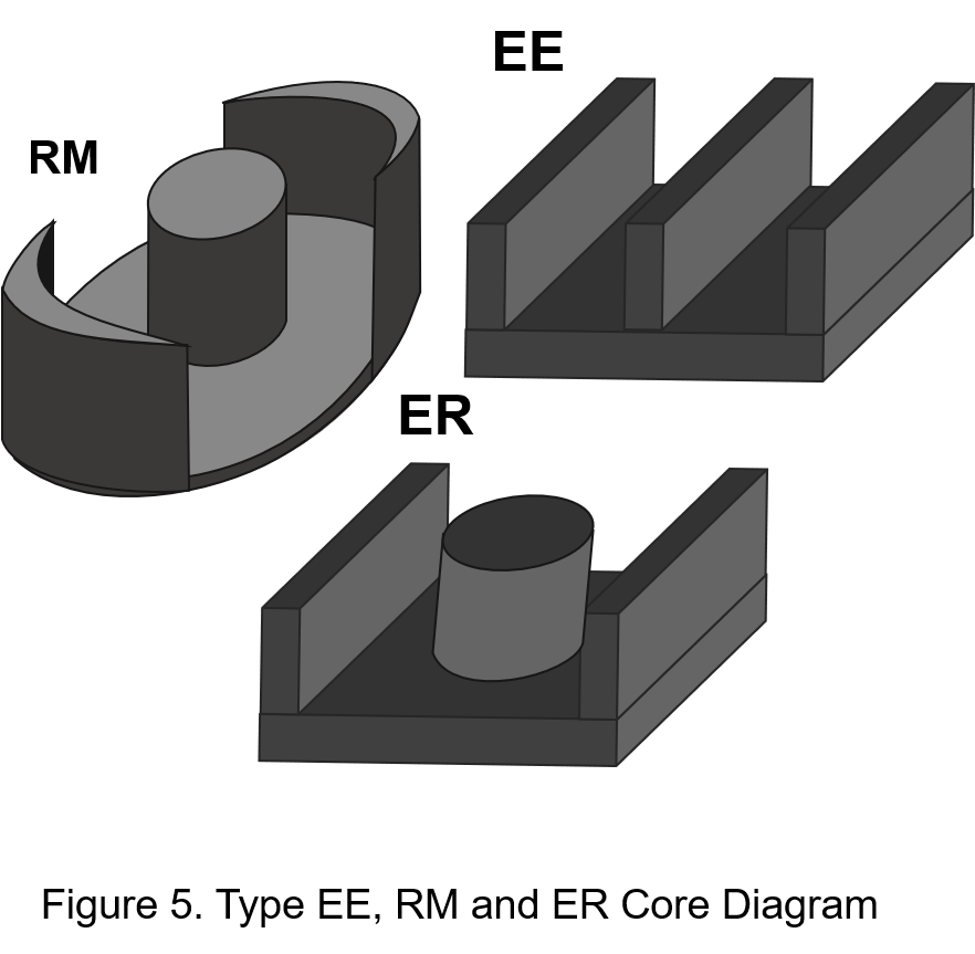
To avoid transformer saturation, planar transformers typically use ferrite soft magnetic materials to form EE-type, RM-type, or ER-type cores. The goal is to achieve higher inductance with fewer turns of the winding, as shown in the diagram below.
When the core saturates, the effective inductance of the transformer decreases, reducing voltage conversion efficiency. The inductance (𝐿) of a transformer is related to the number of turns in the winding (𝑁), the permeability of the magnetic material, and the cross-sectional area of the core (𝐴𝑒). The formula for calculating inductance is as follows:

Where:
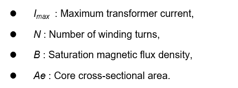
From the formula, it can be seen that planar transformers with fewer turns require cores with larger cross-sectional areas to increase inductance and avoid saturation. Additionally, the flat core structure of planar transformers increases the surface area for heat dissipation, effectively solving the thermal issues of traditional transformers.
3. Design Considerations
Winding Layout:The width (𝑊𝑡) and thickness (𝐻) of the PCB copper foil winding are determined based on the peak current, as expressed in the following formula:

Where:
- I : Peak current,
- K : Correction factor (typically 0.024 for inner copper layers and 0.048 for outer layers),
- T : Maximum temperature (with copper’s melting point at 1060℃)
The spacing between windings affects the parasitic capacitance. Therefore, winding layouts must consider circuit requirements and avoid overly tight arrangements. The diagram below illustrates the winding layout of a planar transformer.
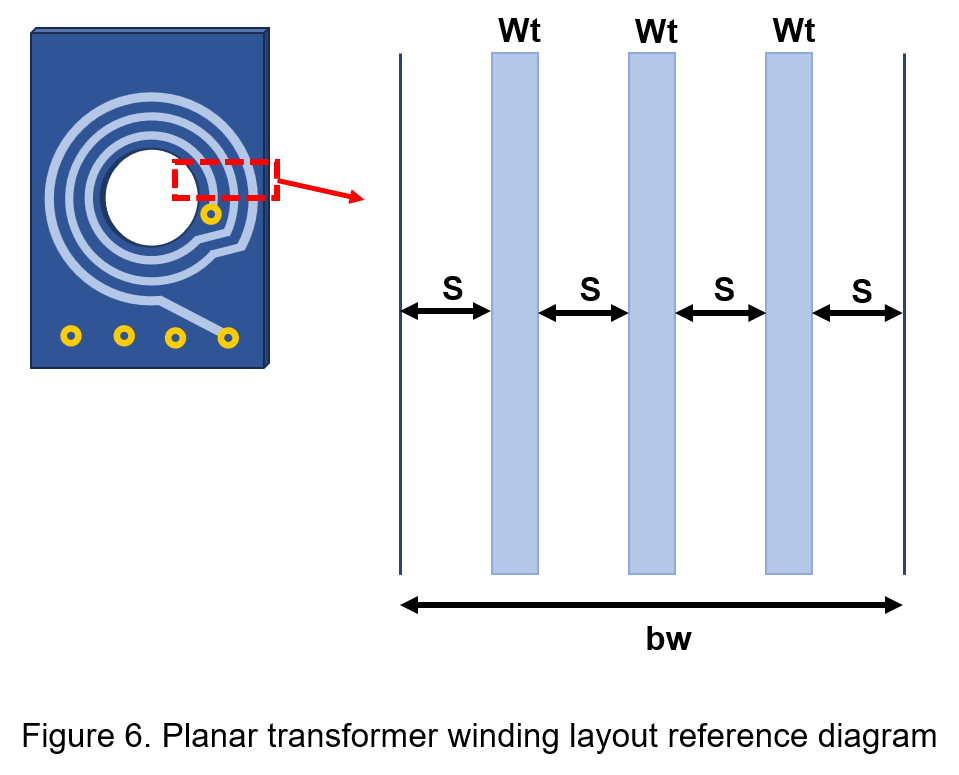

Where:
- bw : Core width,
- S : Winding gap per turn,
- Ni : Number of turns per layer.
The winding trace width is inversely proportional to the number of turns. Choosing appropriate trace width and spacing ensures lower leakage inductance and parasitic capacitance.
- Insulation Materials:The higher the dielectric constant of the insulation material, the higher the parasitic capacitance of the transformer. Therefore, when selecting insulation materials, the dielectric constant must be considered to choose materials that effectively reduce parasitic capacitance.
By following these design considerations, planar transformers can achieve high performance and reliability in practical applications.
Transformer Comparison Table
Compared to traditional wound transformers, planar transformers are more suitable for power converters, especially in high-frequency applications. The table below provides a comparison of the key characteristics of both types.
| Planar Transformers | Wire-Wound Transformers | |
| Conversion Efficiency | High | Low |
| Leakage Inductance | Low | High |
| Parasitic Capacitance | High | Low |
| Size | Small | Large |
| Thermal performance | Good | Poor |
| Reliability | Good | Poor |
| High frequency application | Good | Poor |
Conclusion
Planar transformers offer significant advantages in high-frequency power converters. By replacing traditional copper wire windings with PCB traces, planar transformers effectively reduce core and copper losses, improving overall efficiency and reliability while enabling more compact designs.
Furthermore, the planar structure enhances thermal performance, providing more uniform heat distribution in power converters and improving system stability. These benefits position planar transformers as a superior alternative to traditional wound transformers, making them a critical component in advancing power converter technologies.
CTC is service provider for high-end power modules (DC to DC Converter and AC to DC Converter) for critical applications worldwide since 1987. We aim to be business generator and a virtual business unit. CTC is your own team with 35 years of experience for a strong business program from market research, product definition & development, supply chain management and total technical services.
CTC is the only corporation certificated with ISO-9001, IATF-16949, ISO22613(IRIS, AFNOR silver certificate), and ESD/ANSI-2020. We can 100% ensure not only the product, but also our workflow and service to match quality management system for every high-end application from the very beginning. From design to manufacturing and technical support, every single detail is operated under highest standard.

