

You are here
Back to topInterconnecting multiple system - Novel solution for CAN bus application
Oct 23, 2018
Controller Area Network (CAN) is a communication protocol which developed by BOSCH company which has been standardized globally in 1993 to ISO-11898. One of the feature of CAN system is with high flexibility in maintenance. It can be installed easily to workstation without any adjustment on hardware or software. Besides, it has the adjustable priority of data transmission. There is no delay to the higher priority message, and the lower priority message is automatically retransmitting after the end of the dominant message.
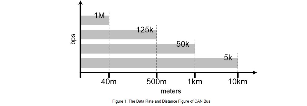
The data transmission rate is decided by the distance of CAN bus. During the transmission period, signal loss is not acceptable. As shown in Figure 1, when the transmission rate is up to 1 Mbps, the max transmission distance is 40 meters. And if the transmission rate is 5 kbps, the transmission distance is up to 10 kilometers. The meaning of transmission distance is not the length of single bus, but the total length of mainstream and each branch.
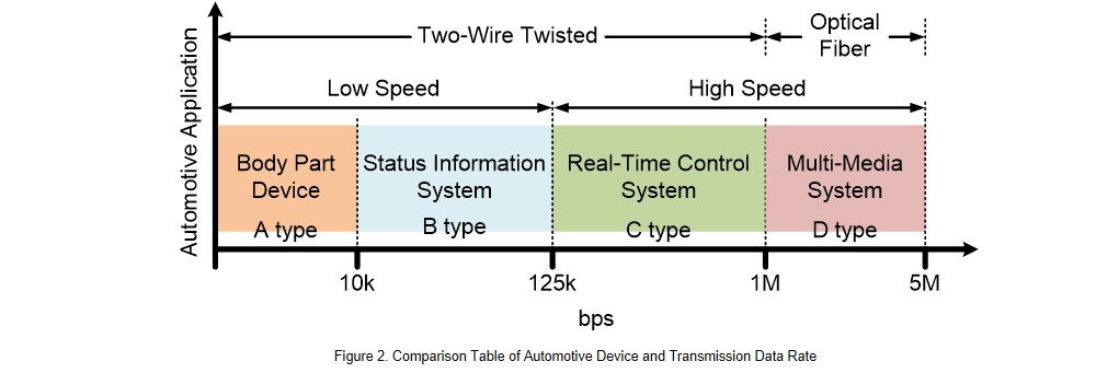
When the device is transmitting signals through CAN bus network, there is a suitable transmit rate for different devices. Take automotive device as an example, if the rate is below 1 Mbps, it's using a twisted pair CAN bus as transmission network. If the rate is over 1 Mbps, the communication network is using fiber optic.
As shown in Figure 2, the device can be divided into 2 categories in general: low or high speed. The transmission rate below 10 kbps are mostly body system, such as power seats, lighting system, door locks, power windows, and so on. For status information system such as air conditioning systems, dashboard, driving information display devices, fault diagnosis systems…etc., the data rate is between 10 kbps and 125 kbps.
The transmission rate of real-time control system with high transmit speed is between 125 kbps and 1 Mbps. Such as gearboxes, engine control systems, brake systems, suspension control systems, or airbags. The multi-media system with transmission rate higher than 1 Mbps, is car audio and video system.
Non-isolated or isolated CAN transceiver can be chosen during the transmission of signal through CAN bus in the same ground system. However, if the two devices are in separate ground systems, only isolated CAN transceiver can be used, as shown in Figure 3. Since the non-isolated transceiver has poor anti-interference ability, it can only be used in a single transmission path with the same ground system.
Isolated transceiver is recommended to be used to some condition. For example, (I) long and multiple-transport paths, (II) the signal is transmitted across different ground systems, (III) the signal which is susceptible to noise interference by parasitic inductance or capacitance. An isolated transceiver is useful to avoid signal interference or data loss.
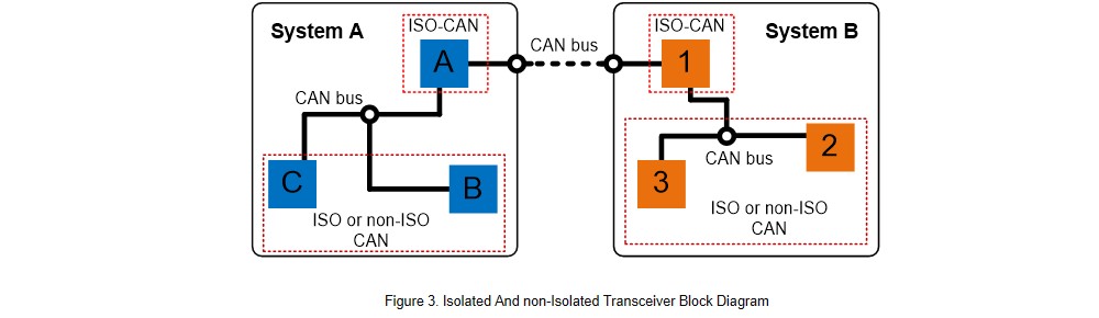
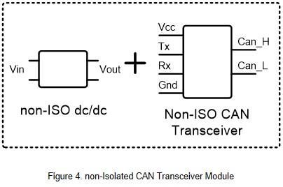
Figure 4 shows the non-isolated transceiver module. It consists of non-isolated CAN transceiver and non-isolated power supply. The advantage of this method is low BOM cost. It’s often used in the simple transmission path. The disadvantage is that it’s easier to get interference during signal transmission so you need to pay more attention to noise interference.
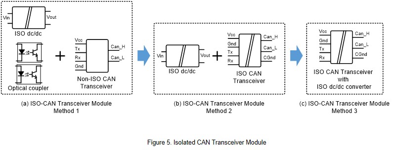
Based on the safety requirements and the purpose of preventing packet loss during transmission, isolated CAN transceivers are commonly used in communication system. There are three types of application methods. The first method is using optical couplers for galvanic isolation, along with non-isolated CAN transceivers to transmit the signals. An additional isolated power supply is needed, as shown in Figure 5(a).
The advantage of this method is that the optical coupling is cheaper and with high selectivity. However, the speed of signal transmission is limited by optical coupling, and the overall power loss and layout space is larger.
Another method is to use an isolated CAN transceiver with an isolated power, as shown in Figure 5(b). The signal transmission of this method is not restricted by the optical coupling. It is with faster transmission speed and the power loss is low.
Using isolated transceiver is a popular application for communication system. However, the disadvantage is it needs more layout space for an isolated power supply.
The latest application method is a CAN transceiver with built-in isolated power supply, as shown in Figure 5(c). Not only with faster transmission and lower power consumption, it also helps to smaller the product as there is no space needed for an additional isolated power supply.
Application Profile
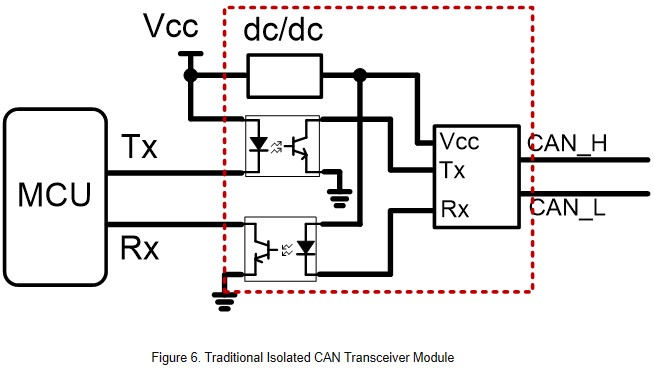
Figure 6 shows an application circuit using the optically coupled and non-isolated transceiver. The MCU transmits and receives signals through optical coupling. And the isolated signals are transmitted to the communication network through the transceiver. The overall part count and layout space are large, and the signal transmission speed is limited by optical coupler.
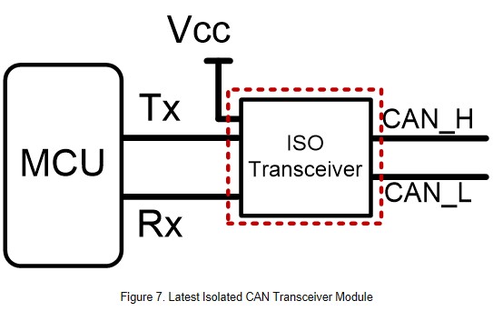
Now the latest application is shown in Figure 7. It can transfer signals between communication network and MCU through a single module, without complicated parts.
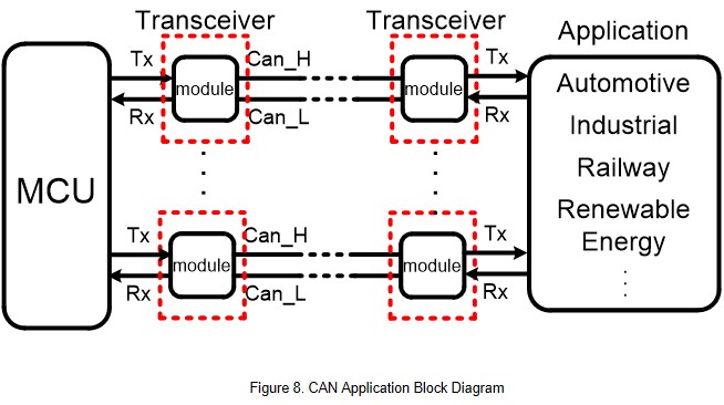
CAN was originally used as a vehicle communication interface in the automotive industry. With the development of communication networks, many industries have begun to implement CAN. For example, industrial application, railway or renewable energy, as shown in Figure 8. The microcontroller transmits the differential control signal by CAN transceiver, so the signal can be transmitted to a designated application in a great distance.
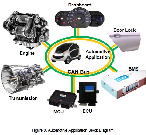
The high transmission speed and high reliability of the CAN bus replaces the complex traditional automotive electronic network. Figure 9 is the block diagram of CAN bus which is used in the automotive electronic system. As shown in the figure, the control unit can communicate with each other via the CAN bus, such as controlling the engine, gearbox or door lock through MCU or ECU, or display battery information on the dashboard.
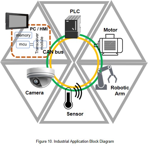
There are also many industrial applications using the CAN transceiver such as industrial communication system in smart factories. As shown in Figure 10, the human machine interface (HMI) transmits control signals through the CAN transceiver to control end devices or instrumentation, such as robotic arms, gates or motor. At the same time, it can also receive temperature or humidity information collected by sensor, or video image by camera.
Except for the automotive application, CAN bus is often used to transmit and receive information in railway applications and new energy applications. Figure 11 is a schematic diagram of the railway application. It can be seen from the figure that the train's propulsion system and the door switch system are transmitting signals through CAN bus, as well as the temperature and humidity measurement system inside the train cabin, and shows the BMS status to human-machine interface system.
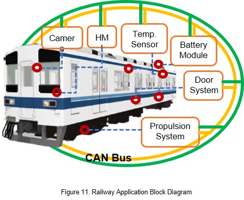
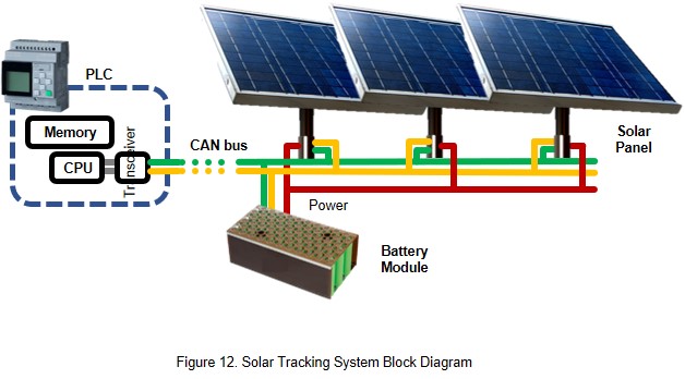
Figure 12 is the block diagram of renewable energy application. The controller transmits the command signal to the motor through the CAN network to control the direction of the solar panel. With the right angle, the solar panel can provide maximum power point. In addition, the status of the battery module can also be known from the CAN network.
CTC is a professional service provider for high-end power supply modules (AC to DC Converter and DC to DC Converter) for critical applications worldwide since 30 years. Our core competence is to design and deliver products with leading technologies, competitive pricing, extremely flexible lead-time, global technical service and high-quality manufacturing (Made In Taiwan).
CTC is the only corporation certificated with ISO-9001, IATF-16949, ISO22613(IRIS), and ESD/ANSI-2020. We can 100% ensure not only the product, but also our workflow and service to match quality management system for every high-end application from the very beginning. From design to manufacturing and technical support, every single detail is operated under highest standard.