

You are here
Back to topWhat is clearance and creepage distance of insulation?
Designers must understand the principles of safety requirements in order to design safe equipment. Not only considered the normal operating conditions of the equipment, but also possible failure conditions, expected failure, and environmental influences such as temperature, altitude, pollution, and humidity. Safety standards have clear statements and regulations on manufactured equipment and parts to provide safe and high-quality products to end-users. This article is mainly aimed at preventing electric shock damage to the human body. To achieve electric shock protection, electronic equipments must have an effective insulation method, which can be divided into clearance and creepage distance and solid insulation materials. This article will focus on the clearance and creepage distance of electronic products.
1. Classes of equipment with respect to protection from electric shock
There is no dangerous voltage, and this energy does not cause pain or injury.
The equipment has protection against electric shock, in addition to basic insulation, there is supplementary insulation or provide reinforced insulation. This type of equipment does not provide protective grounding, but itself can provide protection from electric shock.
- Class I equipment
In addition to basic insulation, it also includes additional protective measures. If the basic insulation fails, the external wires connect to the protective earthing conductor to conduct dangerous currents to the earth.
- Class II equipment
The equipment has protection against electric shock, in addition to basic insulation, there is supplementary insulation or provide reinforced insulation. This type of equipment does not provide protective grounding, but itself can provide protection from electric shock.
- Class III equipment
There is no dangerous voltage, and this energy does not cause pain or injury.
2. Requirement of distance
2.1 Definition of clearance and creepage
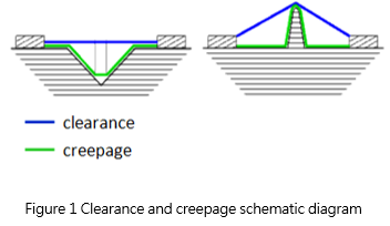
- Clearance: In the "line of sight" distance or the shortest air path between two conductors. The shortest distance that can achieve insulated through the air.
- Creepage: The shortest distance between two conductors along the insulating surface.
- Creepage must be greater than or equal to clearance.
2.2 Important factor in determining distance
The creepage and clearance will have different considerations due to different factors such as product use conditions or environment. As described in IEC 62368-1, the creepage and clearance will be determined according to the following conditions:
- Input voltage
- Insulation
- Material group
- Pollution degree
- Overvoltage category
- Altitude
2.3 Insulation type
Insulation type can be defined as standards for five different purposes:
- Basic insulation
Single-layer insulation can provide users with basic protection against electric shock.
2. Double insulation
Double insulation includes both basic insulation and supplementary insulation.
3. Functional insulation
The necessary insulation between the conductive parts in the equipment so that the equipment can operate normally so is not a safety consideration for users.
4. Reinforced insulation
A single-layer insulation system can reach the level of protection against electric shock equivalent to double insulation.
5. Supplementary insulation
The second layer of insulation independent of the basic insulation can protect the user from dangerous voltage when the basic insulation fails.
2.4 Material Group
The material group is distinguished by the Comparative Tracking Index (CTI). CTI is used to measure the electrical breakdown (tracking) properties of an insulating material.
Material Group I:600 ≤ CTI
Material Group II:400 ≤ CTI < 600
Material Group IIIa:175 ≤ CTI < 400
Material Group IIIb:100 ≤ CTI < 175
If it is an unknown material group, it is assumed to be IIIb.
2.5 Pollution degree
IEC 62368-1 defines the different degrees of pollution that products exist in the operating environment:
- Pollution degree 1
No pollution or only dry non-conductive pollution occurs. For example, equipment, components, or subassemblies that excluded from dust and moisture through sealed packaging.
- Pollution degree 2
Only non-conductive pollution occurs, except for occasional temporary conduction caused by expected condensation. Suitable for general laboratory or office environment.
- Pollution degree 3
Conductive pollution occurs, or dry non-conductive pollution occurs due to expected condensation. For example, equipment is used in the factory.
2.6 Overvoltage category
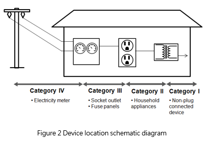
Determine the overvoltage category for each device connected to the power supply, and distinguish it according to the maximum transient voltage of the device connected to the input terminal, as shown in the following figure as the device application location.
- Overvoltage category I: The equipment has taken measures to reduce power transients.
- Overvoltage category II: Permanent or pluggable equipment connected through the building wiring
- Overvoltage category III: Equipment will be an integral part of the building wiring
- Overvoltage category IV: Equipment is connected to the main power supply that enters the building.
2.7 Altitude
The clearance of equipment set in the IEC 62368-1 is all used under 2000 meters above sea level. If there is a high altitude requirement, you need to multiply the obtained clearance by the factor required for different altitudes, according to Table 1.
|
Altitude m |
Normal Barometric Pressure kPa |
Multiplication Factor for Clearance | Multiplication Factor for Electric Strength Test Voltage | |||
| ≥0.01 mm to ≤0.0625 mm | ≥0.0625 mm to <1 mm | ≥ 1 mm to <10 mm | ≥10 mm to <100 mm | |||
| 2,000 | 80.0 | 1.00 | 1.00 | 1.00 | 1.00 | 1.00 |
| 3,000 | 70.0 | 1.14 | 1.05 | 1.05 | 1.07 | 1.10 |
| 4,000 | 62.0 | 1.29 | 1.10 | 1.10 | 1.15 | 1.20 |
| 5,000 | 54.0 | 1.48 | 1.17 | 1.16 | 1.24 | 1.33 |
| Linear interpolation may be used between the nearest two points, the calculated minimum multiplication factor being rounded up to the next higher 0.01 increment. | ||||||
2.8 Solid insulation material
Power converters often use the potting compound against dust and moisture, and gel material also can use as insulation material. In the IEC 62368-1, it is mentioned that gel is regarded as an insulating material. Therefore, the insulation methods include meeting the requirements of distance and solid insulating materials also. If the gel materials used as insulation, the characteristic needs to be evaluated such as flammability, RTI, thermal conductivity, pressure resistance, and so on.
3. The example of distance calculation
Generally, the distance through insulation for power converters refers to the distance from the primary side to the secondary side. Take AC/DC converter as an example, the input voltage is 100-240Vac.
According to Table 2, when the overvoltage level is II, the main transient voltage is 2500 Vpeak. And Correspond to Table 3, the minimum clearance for basic insulation is 1.5 mm, the clearance for reinforced insulation needs to reach 3.0 mm. Refer to Table 4 for the creepage. The minimum creepage needs 2.5 mm for basic insulation, and the distance for reinforced insulation is twice longer than the basic insulation, so the creeping for reinforced insulation must reach 5.0 mm.
|
AC mains voltage a up to and including |
Mains transient voltage b V peak |
||||
| Vr.m.s. | V peak c | Overvoltage category | |||
| I | II | III | IV | ||
| 50 | 71 | 330 | 500 | 800 | 1500 |
| 100 d | 141 | 500 | 800 | 1500 | 2500 |
| 150 e | 210 | 800 | 1500 | 2500 | 4000 |
| 300 f | 420 | 1500 | 2500 | 4000 | 6000 |
| 600 g | 840 | 2500 | 4000 | 6000 | 8000 |
|
a For equipment designed to be connected to a three-phase 3-wire supply, where there is no neutral conductor, the a.c. mains supply voltage is the line-to -line voltage. In all other cases, where there is a neutral conductor, it is the line-t0-neutral voltage. b The mains transient voltage is always one of the values in the table. Interpolation is not permitted. c See 5.4.2.5.1. d In Japan, the value of the mains transient voltages for the nominal a.c. mains supply voltage of 100 V is determined from columns applicable to the nominal a.c. mains supply voltage of 150 V. e Including 120/208 V and 120/240 V. f Including 120/400 V and 277/480 V. g Including 400/690 V. |
|||||
| Required withstand voltage |
Basic insultation or supplementary insulation mm |
Reinforced insulation mm |
||||
|
V peak or d.c. up to and including |
Pollution degree | Pollution degree | ||||
| 1 | 2 | 3 | 1 | 2 | 3 | |
| 330 | 0.01 | 0.2 | 0.8 | 0.04 | 0.6 | 1.5 |
| 400 | 0.02 | 0.07 | ||||
| 500 | 0.04 | 0.10 | ||||
| 600 | 0.06 | 0.14 | ||||
| 800 | 0.10 | 0.5 | ||||
| 1000 | 0.15 | 0.6 | ||||
| 1200 | 0.25 | 0.9 | ||||
| 1500 | 0.5 | 1.5 | ||||
| 2000 | 1.0 | 2.2 | ||||
| 2500 | 1.5 | 3.0 | ||||
| 3000 | 2.0 | 3.8 | ||||
| 4000 | 3.0 | 5.5 | ||||
| 5000 | 4.0 | 8.0 | ||||
|
RMS working voltage up to and including v |
Pollution degree | ||||||
| 1 | 2 | 3 | |||||
| Material group | |||||||
| I, II, IIIa, IIIb | I | II | IIa, IIb | I | II |
IIIa, IIIb see Note |
|
| 10 | 0.08 | 0.4 | 0.4 | 0.4 | 1.0 | 1.0 | 1.0 |
| 12.5 | 0.09 | 0.42 | 0.42 | 0.42 | 1.05 | 1.05 | 1.05 |
| 16 | 0.1 | 0.45 | 0.45 | 0.45 | 1.1 | 1.1 | 1.1 |
| 20 | 0.11 | 0.48 | 0.48 | 0.48 | 1.2 | 1.2 | 1.2 |
| 25 | 0.125 | 0.5 | 0.5 | 0.5 | 1.25 | 1.25 | 1.25 |
| 32 | 0.14 | 0.53 | 0.53 | 0.53 | 1.3 | 1.3 | 1.3 |
| 40 | 0.16 | 0.56 | 0.8 | 1.1 | 1.4 | 1.6 | 1.8 |
| 50 | 0.18 | 0.6 | 0.85 | 1.2 | 1.5 | 1.7 | 1.9 |
| 63 | 0.2 | 0.63 | 0.9 | 1.25 | 1.6 | 1.8 | 2.0 |
| 80 | 0.22 | 0.67 | 0.95 | 1.3 | 1.7 | 1.9 | 2.1 |
| 100 | 0.25 | 0.71 | 1.0 | 1.4 | 1.8 | 2.0 | 2.2 |
| 125 | 0.28 | 0.75 | 1.05 | 1.5 | 1.9 | 2.1 | 2.4 |
| 160 | 0.32 | 0.8 | 1.1 | 1.6 | 2.0 | 2.2 | 2.5 |
| 200 | 0.42 | 1.0 | 1.4 | 2.0 | 2.5 | 2.8 | 3.2 |
| 250 | 0.56 | 1.25 | 1.8 | 2.5 | 3.2 | 3.6 | 4.0 |
4. Measurement of creepage distances and clearances
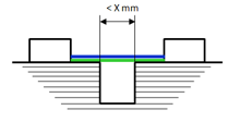
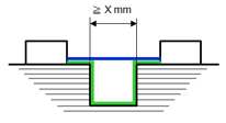
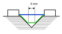
The following are several measurement examples of clearance and creepage. The value of X is listed in IEC 62368-1 according to the pollution degree, as shown in Figure 7. The width of the groove or gap should be noted, whether the distance exceeds X mm. If the width of the groove is less than X mm, the groove can be ignored. If the width of the groove is greater than or equal to X mm, the creepage distance must be measured along the groove contour.
。
|
Pollution degree (see 5.4.1.6) |
X mm |
| 1 | 0.25 |
| 2 | 1.00 |
| 3 | 1.50 |
- Note
![]()
- The path under consideration includes parallel or converging-sided grooves with any depth and width less than X mm. The clearance and creepage are directly measured across the groove.
- The path under consideration includes parallel or converging-sided grooves with any depth and width equal to or greater than X mm. The clearance is the distance of the "line of sight", and the creepage distance path follows the contour of the groove.
- The path under consideration includes V-shaped grooves with an internal angle less than 80° and a width greater than X mm. The clearance is the "line of sight" distance, and the creepage distance path follows the contour of the groove but "short-circuits" the bottom of the groove by X mm link.
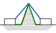
- The path under consideration includes rib-shaped protrusions, the clearance distance is the shortest air path over the top of the protrusions, and the creepage distance along the surface follows the rib-shaped protrusions.
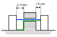
- The path under consideration includes an uncemented joint width of the groove on one side less than X mm, and the other equal to or greater than X mm. The clearance distance on the left is the distance of the "line of sight", and the creepage distance path follows the contour of the groove. The clearance distance and creepage on the right is the distance of the "line of sight".
5. Summary
In electronic products, clearance and creepage are set to protect the users and prevent personal injury and property losses. Therefore, different factors such as the environment and location of the product must be considered for design the power converter, and different levels of requirements will need to be met. Therefore, the clearance and creepage must be considered in the design and meet the standard to truly protect the users.
CTC is a professional service provider for high-end power supply modules (AC to DC Converter and DC to DC Converter) for critical applications worldwide since 30 years. Our core competence is to design and deliver products with leading technologies, competitive pricing, extremely flexible lead-time, global technical service and high-quality manufacturing (Made In Taiwan).
CTC is the only corporation certificated with ISO-9001, IATF-16949, ISO22613(IRIS), and ESD/ANSI-2020. We can 100% ensure not only the product, but also our workflow and service to match quality management system for every high-end application from the very beginning. From design to manufacturing and technical support, every single detail is operated under highest standard.