

You are here
Back to topRemote ON/OFF
A power converter with the remote control (CTRL) function is a useful way to save power or limit inrush current. This article will introduce the control parameters defined in the general specifications and guide users to follow simple rules to achieve this function. Finally, implement the converter to connect the external circuit, and display the function performance of the converter and the control pin through the waveform.
1. Control Configurations
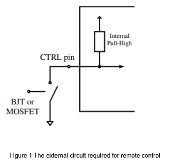
The converter with remote control function makes the converter in standby mode or restart it through the control pin (CTRL). The control method is simple, and the converter can be controlled only through the switching components, as shown in Figure 1. For users who value standby power consumption or need timing control, the remote control is a favorable function.
The common remote control configurations can divide into positive logic and negative logic. Positive logic means that the control signal is high, and the converter operates normally. Negative logic means that the control signal is low, and the converter operates normally. However, the detailed potential control methods need to refer to the specifications.
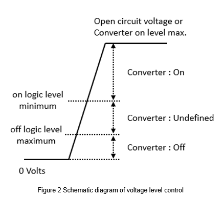
The voltage parameters for controlling the CTRL define in the specification. The schematic diagram of the positive logic control mode shows in Figure 2. When the external signal is lower than the off logic level maximum required, the converter shuts down. When the external signal is higher than on logic level minimum required, the converter starts up. If the external signal is between the highest off logic voltage and lowest on logic voltage, the converter is in an undefined state, and there is no guarantee that the converter is on or off. Therefore, it is not recommended that converters set the control signal within this range.
2. Application
Different control modes need a suitable external circuit to achieve. Table 1 shows the logic and operating range of remote control excerpt from the product specification. As shown in the figure, if the control pin is open or receives a high voltage level (3~12Vdc), the converter operates normally. Conversely, if the control pin is short-circuited or receives a low voltage level (0~1.2Vdc), the converter is turned off, and there is no voltage output.
| Parameter | Conditions | Min. | Typ. | Max. | Unit |
| Remote on/off | DC-DC on | Open or 3V < Vr <12V | |||
| DC-DC off | Short or 0V < Vr <1.2V | ||||
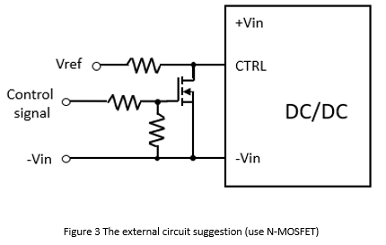
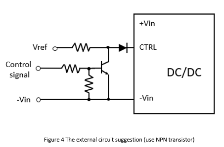
Figure 3 shows the recommended external circuit for the remote control function. Take the above specifications as an example, when the external control signal is high, the CTRL voltage level is low, and then the converter turns off. When the control signal is low, the CTRL voltage level is high, and then the converter operates normally. Vref is the reference voltage, generally 5Vdc. The N-MOSFET can also be replaced with an NPN transistor, as shown in Figure 4. However, it is recommended to connect a forward diode in series to prevent the CTRL from malfunctioning due to external noise.
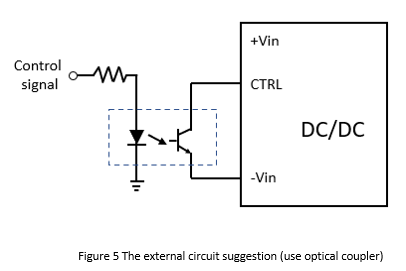
If the control circuit needs to be isolated, the optical coupler could be used as an isolator, as shown in Figure 5. The control mode is the same as mentioned above. When the external control signal is high, the CTRL voltage level is low, and then the converter turns off. When the control signal is low, the CTRL voltage level is high, and then the converter operates normally.
The external control circuit has multiple types. When the control logic changes, the external circuit should be different. For example, Table 2 is an unusual control logic. When the control pin is at a high voltage level, 5~10Vdc, the converter turns off. When the control pin is open, the converter operates normally. Under such control logic, the external circuit shown in Figure 3 cannot control the converter, so the wiring method must change.
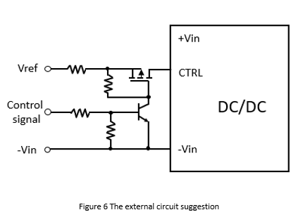
Figure 6 shows the external circuit for this application. When the external control signal is high, the NPN transistor turns on. The gate voltage of the P-MOSFET shorts to the ground and make it turn on. At this time, CTRL is high, and the converter turns off. When the external signal is low, the NPN transistor turns off. The gate voltage of the P-MOSFET is high voltage level to turn it off. At this time, the CTRL is open, and the converter operates normally. Vref is the reference voltage. The NPN transistor in the figure can also replace with an N-MOSFET.
| Parameter | Conditions | Min. | Typ. | Max. | Unit |
| Input Voltage Range | 18 | 24 | 36 | Vdc | |
| Output Voltage | 12 | Vdc | |||
| Remote on/off | DC-DC on | Open | |||
| DC-DC off | 5V ≤ Vr < 10V | ||||
3. Example
Next, the DC-DC power converter will connect with an external circuit to realize the remote control function. The specifications of the remote control are as shown in Table 3. When the CTRL voltage level is 3.5~15Vdc or open, the converter operates normally. When the CTRL voltage level is 0~1.2Vdc or short, the converter turns off. First, choose N-MOSFET as the switching components, and the actual circuit shows in Figure 7.
| Parameter | Conditions | Min. | Typ. | Max. | Unit |
| Input Voltage Range | 9 | 24 | 36 | Vdc | |
| Output Voltage | 5 | Vdc | |||
| Remote on/off | DC-DC on | Open or 3.5V ~ 15V | |||
| DC-DC off | Short or 0V ~ 1.2V | ||||
| Input Current (Remote off mode) | 2 | mA | |||
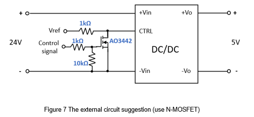
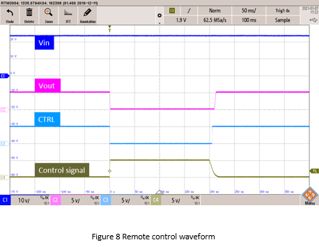
Figure 8 shows the actual measured signals, including converter input voltage, output voltage, CTRL, and external control signals. When the external control signal is high, the N-MOSFET turns on, the CTRL decreases to 0Vdc, and the converter has no output. On the contrary, when the external control signal is low, the N-MOSFET is cut off, the CTRL voltage level rises to 5Vdc, and the converter operates normally.
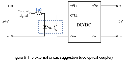
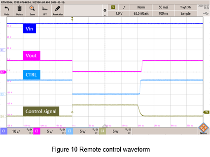
Another way is that an optical coupler is used to isolate. The actual circuit shows in Figure 9. This method can isolate the control signal from the converter. Figure 10 shows the measurement signal. When the external control signal is high, the optocoupler turns on, the CTRL decreases to 0Vdc, and the converter has no output. On the contrary, when the external signal is low, the optocoupler cut off, the CTRL voltage level rises to 6.5Vdc, and the converter operates normally.
Summary
Converters with remote control functions are very common in industrial applications, such as robotic arms, power and telecommunications control, or applications that require timing control. Through the simple external circuit introduced in this article, the converter can be turned on or off through the control signal to achieve timing control or power saving requirements.
CTC is a professional service provider for high-end power supply modules (AC to DC Converter and DC to DC Converter) for critical applications worldwide since 30 years. Our core competence is to design and deliver products with leading technologies, competitive pricing, extremely flexible lead-time, global technical service and high-quality manufacturing (Made In Taiwan).
CTC is the only corporation certificated with ISO-9001, IATF-16949, ISO22613(IRIS), and ESD/ANSI-2020. We can 100% ensure not only the product, but also our workflow and service to match quality management system for every high-end application from the very beginning. From design to manufacturing and technical support, every single detail is operated under highest standard.