

You are here
Back to topInsulation in Motor Drive Application
In industrial applications, the most common is the motor control application, such as fans, conveyor belts, robotic arms or electronic compressors. For these applications, it is necessary to control the motor through a Variable Frequency Drive (VFD), and detect the speed or position of the motor through a sensor. Through an appropriate control mechanism, the operating efficiency and accuracy of the motor will be improved.
Due to common input power source of the motor driver is AC source. So, when designing internal circuits, safety measures must be considered to ensure the safety of operators. IEC/UL 61800-5-1 is a safety standard for motor drive systems, this standard defined the level of insulation grade between accessible system and components. This article shows where power converters can be used in motor drives application, as well as the insulation for each application.
Block Diagram for Motor Drive Application
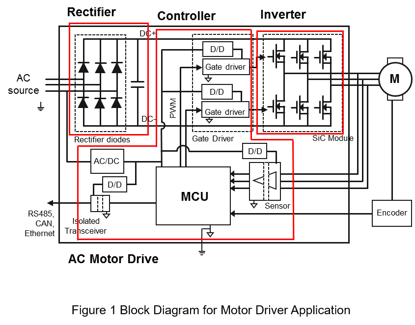
Figure 1 is a block diagram of the motor drive application, which can be divided into several parts
- Rectifier: As block diagram shows, it is used diode to convert the AC power to DC power. Also, PFC converter will increase power consumption and power factor.
- Inverter: Transfer DC power to AC power, in order to control the motor. The inverter commonly uses SiC, GaN or Si MOSFET, and IGBT as power switch.
- Controller: It contains MCU controller, sensors and communication interface. The sensors detect voltage, current, speed and other information, then send this information to MCU. The MCU controls the inverter through PWM signal. Also, the MCU communicates with other system through communication interface.
As Figure 1 shows, isolated converters are used only in the controller, such as AC/DC converter, which provide isolated power from AC source. And isolated DC/DC converter, which provide isolated power to sensors, gate drivers and transceiver.
Following shows the insulation requirement in IEC/UL 61800-5-1 for motor application. Table 1 is the Decisive Voltage Classes (DVC), which classifies different working voltages A to D class. For example, if the input voltage is 230Vac, and it will classify as C class.
| DVC | Limits of working voltage | ||
| A.C. Voltage (rms) | A.C. Voltage (peak) | D.C. Voltage (mean) | |
| A | 25 | 35.4 | 60 |
| B | 50 | 71 | 120 |
| C | 1000 | 4500 | 1500 |
| D | >1000 | >4500 | >1500 |
Table 2 is the circuit protection requirements from IEC/UL 61800-5-1. It shows the insulation requirements of different working voltage levels to ground and other circuits. For example, if the primary side working voltage level is A, and the secondary side working voltage level is C. Refer to table 2, the insulation level requires Protective Separation. The Protective Separation is equal to Reinforce insulation, or Basic insulation with additional Independent insulation.
| DVC | Protection req. | Insulation to earthed | Insulation to conductive part | Insulation to adjacent circuit of DVC | |||
| A | B | C | D | ||||
| A | No | Functional | Functional | Functional | Basic | Protective | Protective |
| B | Yes | Basic | Protective | Basic | Protective | Protective | |
| C | Yes | Basic | Protective | Basic | Protective | ||
| D | Yes | Basic | Protective | Protective | |||
Insulation Requirement
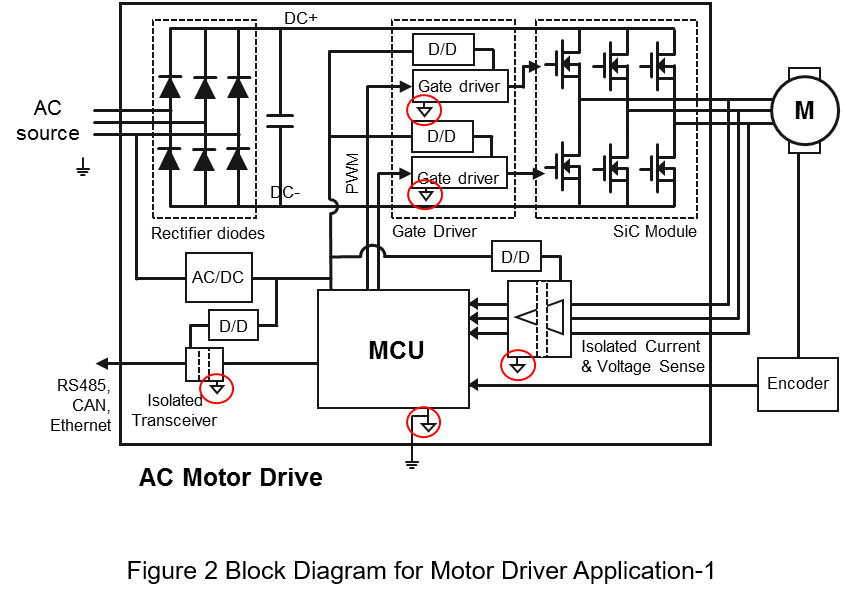
Figures 2 and 3 are common block diagrams of motor drives application. Through Table 1 and 2, the applications in the controller can be classified as below. First, assuming the input source is 380Vac. From Figure 2 we can see
- AC/DC converter
Assuming that the input source is 220Vac, it can be seen from Table 1 that it is C class. In this application, the output voltage is mostly 5Vdc, so it is A class. From Table 2, the insulation level should be Protective Separation.
- Gate Driver Circuit and Isolated Power
The primary side is connected to MCU and Case, and the secondary side provide power to SiC module. From Table 1, the primary side is A class and the secondary side is C class. Refer to Table 2, the insulation level should be Protective Separation.
- Sensors and Isolated Power
The primary side is connected to MCU and Case. And the secondary side is connected to the motor, in order to detect the voltage and current. From Table 1, the primary side is A class and the secondary side is C class. Refer to Table 2, the insulation level should be Protective Separation.
- Transceiver and Isolated Power
The primary side is connected to the MCU, and the secondary side is connected to another system. From Table 1, the both side of the transceiver are A class. From Table 2, the insulation level should be Functional.
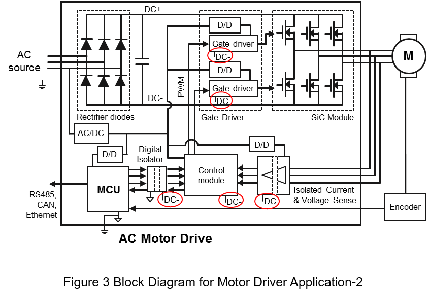
The difference between Figure 2 and Figure 3 is that the primary side of the control module, gate driver, and sensors are connected to the negative terminal of the inverter. And the MCU transmits control signal and receives information through the digital isolator.
Through Table 1 and 2, the applications in the controller can be classified as below. First, assuming the input source is 380Vac. From Figure 3 we can see
- AC/DC converter
The requirement is same as Figure 2, the insulation level should be Protective Separation.
- Gate Driver Circuit and Isolated Power
Both primary and secondary side are connected to the inverter. So, both sides are C level. From Table 2 the insulation level should be Basic.
- Sensors and Isolated Power
The primary side is connected to the control module, and the secondary side is connected to motor. So, both sides are C level. From Table 2 the insulation level should be Basic.
- Digital Isolator and Isolated Power
The primary side is connected to MCU and Case, and the secondary side is connected to the control module. From Table 1, the primary side is A class and the secondary side is C class. Refer to Table 2, the insulation level should be Protective Separation.
- Transceiver and Isolated Power
The requirement is same as Figure 2, the insulation level should be Functional.
From Figure 2 and 3, we can see although they are same motor driver application, but with different application location must correspond to different insulation requirements.
In Figure 2, the ground of the MCU is connected to the Case, the DC/DC converter provide isolated power to isolated gate driver and motor sensor. The insulation of these application needed Protective Separation.
Same as Figure 3. The ground of gate driver and sensors are connected to inverter. So, the insulation only needs Basic. But it needed additional digital isolator for transfer signal. And the insulation needed Protective Separation.
| Note | Figure 2 | Figure 3 | ||
| 1 | AC/DC Converter | Protective Separation | Protective Separation | |
| 2 | Gate Driver | Circuit | Protective Separation | Basic |
| Power | ||||
| 3 | Current & Voltage Sense | Sensor | Protective Separation | Basic |
| Power | ||||
| 4 | Communication Port | Transceiver | Functional | Functional |
| Power | ||||
| 5 | Digital Isolator | Isolator | NA | Protective Separation |
| Power | ||||
Summary
Through the block diagram and the insulation requirements defined in UL 61800-5-1, this artivcle list the insulation required for each part of the motor drive in different applications. So, the designer can choose the appropriate material, also can determined the insulation distance through IEC 62368-1 to ensure the safety of users.
CTC is a professional service provider for high-end power supply modules (AC to DC Converter and DC to DC Converter) for critical applications worldwide since 30 years. Our core competence is to design and deliver products with leading technologies, competitive pricing, extremely flexible lead-time, global technical service and high-quality manufacturing (Made In Taiwan).
CTC is the only corporation certificated with ISO-9001, IATF-16949, ISO22613(IRIS), and ESD/ANSI-2020. We can 100% ensure not only the product, but also our workflow and service to match quality management system for every high-end application from the very beginning. From design to manufacturing and technical support, every single detail is operated under highest standard.