

You are here
Back to topControl Logic Methods for Switching Regulator
The switching regulator provides power for the system and ensures that each circuit can be turned on or off sequentially in a manner that aligns with the design, thereby maintaining system safety and reliability. The logic control methods vary depending on the technological needs of the industry. This article introduces common switching methods for converters and compares the advantages and disadvantages of various control circuits.
Introduction
According to statistics, global energy demand exceeds several gigawatt-hours, and this demand continues to increase every year. Without ways to improve power efficiency, risks such as power blackouts or system instability may occur. The goal of designing the Switch Mode Power Supply (SMPS) module is to pursue a smaller product size, higher power density, and higher conversion efficiency. This ensures that the overall system operation can meet the needs of energy conservation, or even further extend the battery life of electronic products.
Choosing power converters with a remote control function allows the power converter to enter standby mode or restart at specific times through the control pin (CTRL pin). For users who value low standby power consumption or need timing control, the remote control function is a favorable feature.
- Energy Conserve
Keeping electronic products in a high-power state for extended periods can easily lead to hazards and energy waste. For instance, when cars are idling, appropriately shutting off unnecessary high-current paths can help extend battery life.
- Timing Control
With the development of integrated circuits, many circuits are housed on a single chip. This necessitates the use of multiple power converters to supply power simultaneously, leading to the need for time-sequential control and power management.
Firstly, choose converters with a remote control function. Through the control pin (CTRL pin), the power converter enters standby mode during specific working times and only restarts when the other circuits are ready.

- Prevent Inrush Current
When multiple power supplies within a system are activated simultaneously, the input power rapidly charges the input capacitor. This process generates a substantial inrush current, which can inflict destructive damage on components. The use of remote control effectively staggers the start-up times of individual power converters, reducing input current transients. For switching converters, this method is one of the most effective ways to prevent inrush current. Figure 2(a) illustrates that when Converter 1 and Converter 2 are activated simultaneously, the input inrush current spikes dramatically. In contrast, Figure 2(b) shows that when Converter 1 and Converter 2 are activated sequentially, only two minor spikes appear in the input current, and the peak value is significantly lower than the former scenario.

Control Architecture
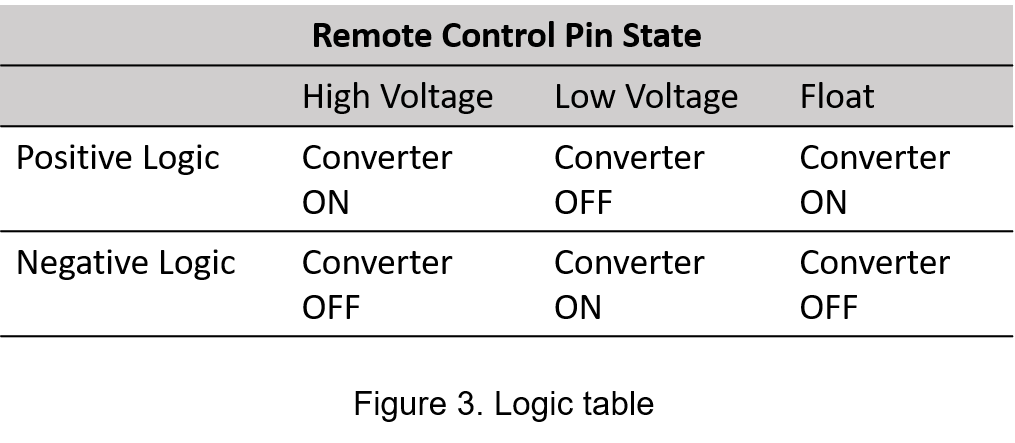
The product specification should provide instructions on how to use the remote control. However, the control logic of power converters is not entirely standardized across different applications. The two common methods are ‘positive logic’ and ‘negative logic’, which are briefly described below:
Positive Logic: When the logic of the Ctrl pin is 1, a high voltage signal above the logic threshold can turn on the power converter. Conversely, when the logic of the Ctrl pin is 0, a low voltage signal turns off the power converter. If the Ctrl pin is left floating, the positive logic converter will continue to operate normally.
Negative Logic: When the logic of the Ctrl pin is 0, a low voltage signal turns on the converter. Conversely, when the logic of the Ctrl pin is 1, a high voltage signal turns off the converter. If the Ctrl pin is left floating, the negative logic converter remains off.
The logic of the control pins is organized in Table 1. However, the high voltage range and low voltage range can vary between different products. Please refer to the product specification before using the power converter.
Recommended Control Methods
Depending on the control modes, appropriate external circuits need to be selected. These external circuits are categorized into isolated and non-isolated types. Figure 4 illustrates the recommended non-isolated external circuit for remote control. As depicted in Figure 4(a)(b), it is evident that general switching elements utilize N-type MOS or NPN-type BJT. During actual operation, it is necessary to connect a forward diode in series to prevent the Ctrl voltage from being disrupted by external noise, which could lead to operational errors. An alternative method involves using a transistor-transistor logic (TTL) circuit to drive the Ctrl pin, as shown in Figure 4(c).
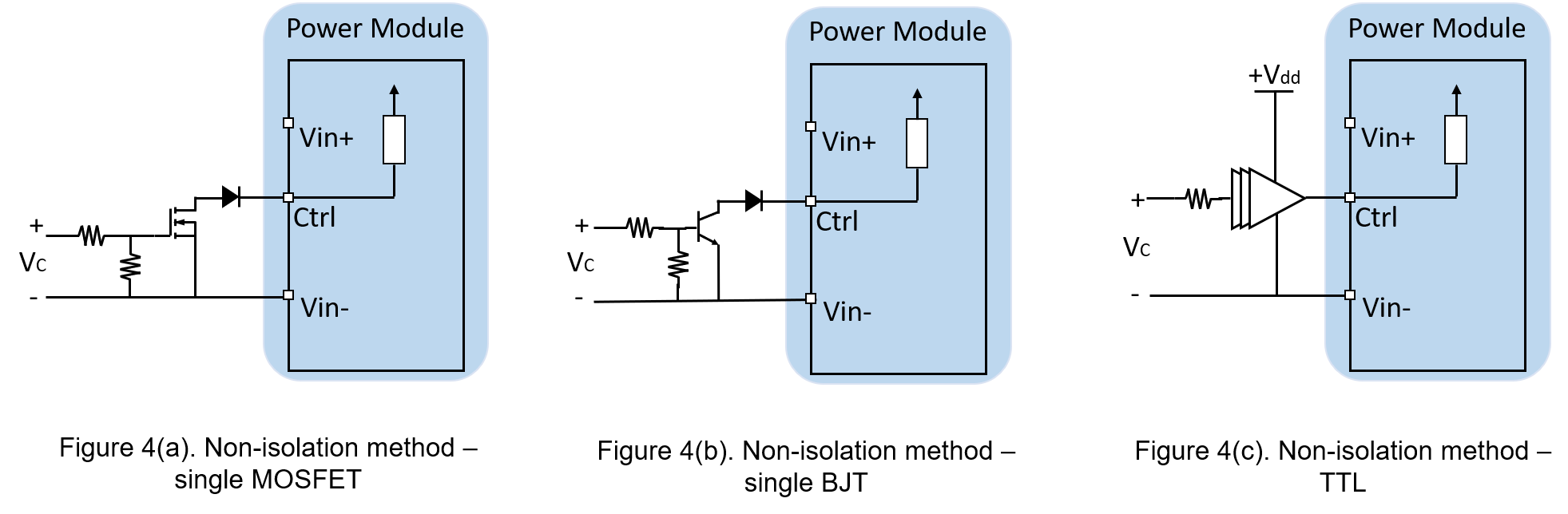
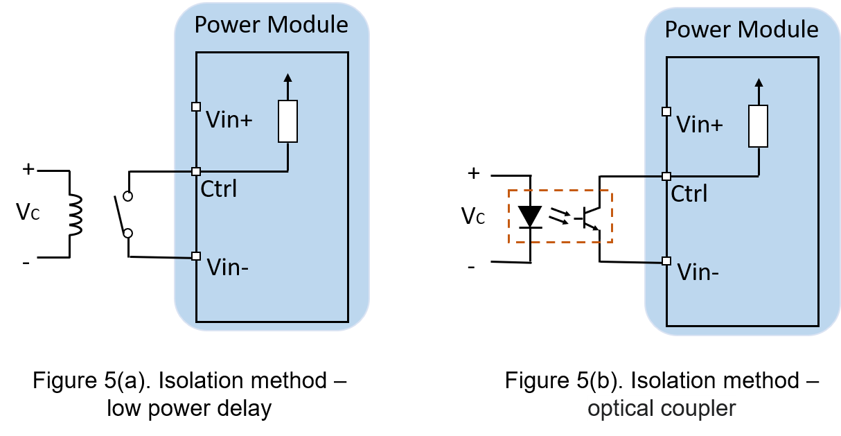
Figure 5 presents the recommended external circuit for an isolated control connection. If the control circuit requires isolation, a relay or an optocoupler can be utilized as an isolator.
Comparing the two cases, the switching speed of the optical coupling method is slower, leading to a significant delay time that can affect the overall system timing. On the other hand, the switching response delay of a non-isolated transistor is minimal. The delay time of the output voltage primarily depends on the time constant, which is the product of the equivalent capacitance at the power converter’s output and the equivalent resistance value.
Experiment
A specific DC-DC converter, as depicted in Figure 4(a), will be utilized with a non-isolated control method. This converter has a wide input voltage range from 9 to 36V. The output voltage of the regulated converter is 5V, with an output power of 30W and an output current of 2.5A. The specifications are provided in Table 1.
| DC to DC Converter | |
| Input voltage | 9V dc -36V dc, typ.:24 Vdc |
| Output voltage | 12 Vdc |
| Output Current | 2.5A |
| Start-up Time | 30mS |
| Remote ON/OFF |
DC-DC ON: Open or 3.5V~15Vdc DC-DC OFF: Short or 0V~1.2Vdc |
| Control Logic | Positive |
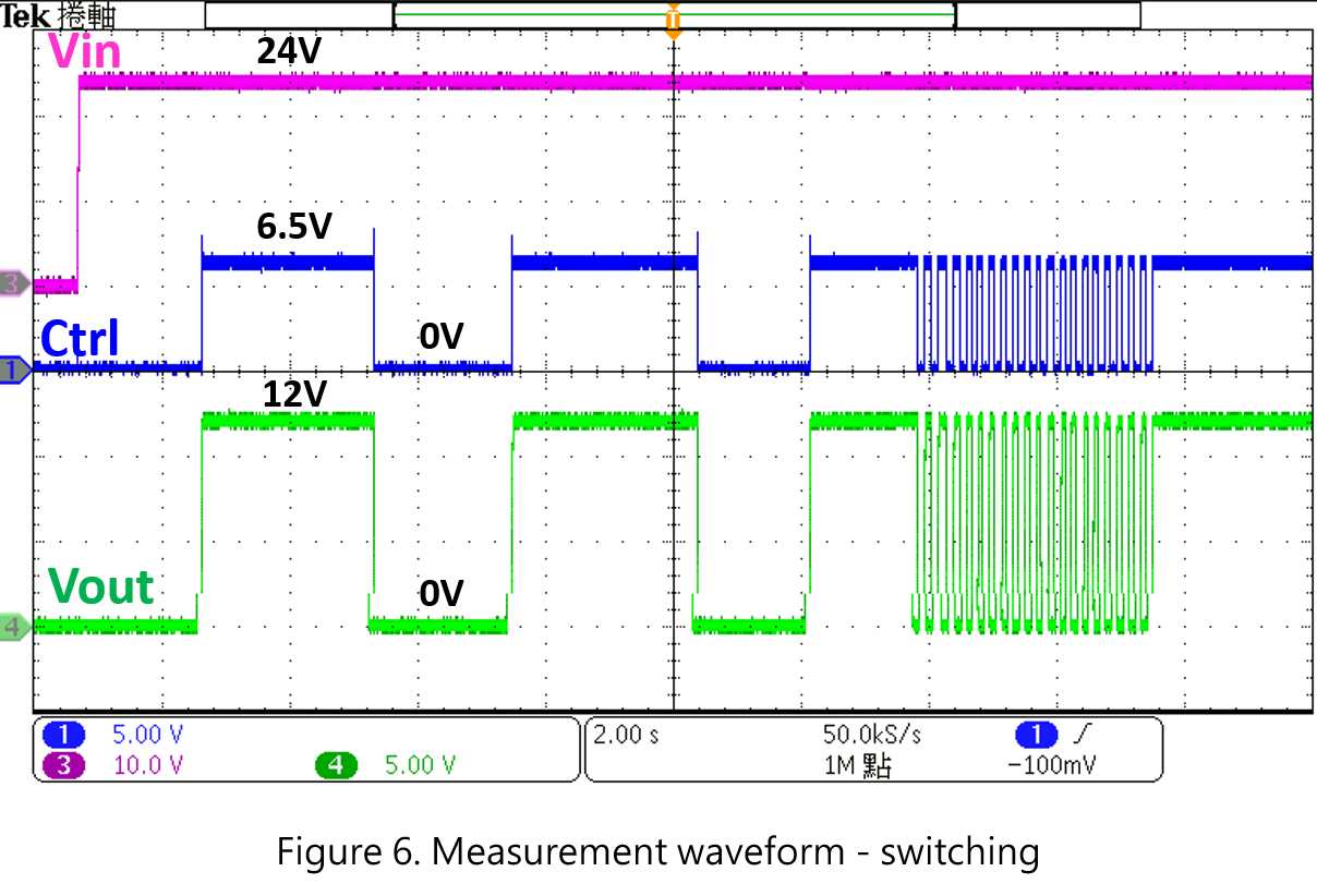
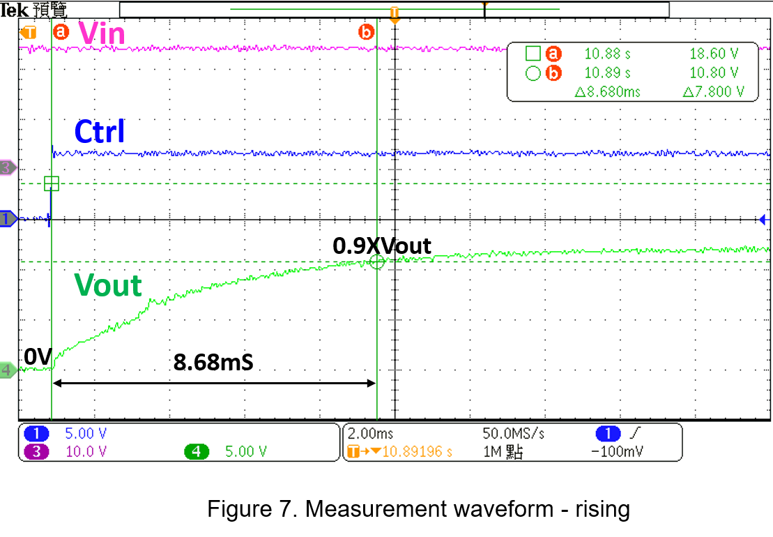
Figure 6 displays the actual measured signals, which include the converter input voltage, output voltage, and control signal voltage. When operating in positive logic mode, the control voltage is 6.5V, exceeding the minimum turn-on voltage. Consequently, the power converter is activated and operates normally. However, it is observed that when the control signal voltage increases to 3.5V, the converter’s rise time is 8.68 milliseconds, and the output voltage becomes 0.9 times the specified value at this moment.
Conclusion
A wide range of electronic products require batteries, and most of these are in standby mode. As such, they can utilize a power converter with a remote control function, which, when paired with external circuits, allows for low static power, sequence control, and prevention of inrush current. This article introduces the remote logic control functions, enumerates the external wiring of both isolated and non-isolated types, compares their differences, and ultimately implements a logic switching controller applicable to isolated converters.
CTC is service provider for high-end power modules (DC to DC Converter and AC to DC Converter) for critical applications worldwide since 1987. We aim to be business generator and a virtual business unit. CTC is your own team with 35 years of experience for a strong business program from market research, product definition & development, supply chain management and total technical services.
CTC is the only corporation certificated with ISO-9001, IATF-16949, ISO22613(IRIS, AFNOR silver certificate), and ESD/ANSI-2020. We can 100% ensure not only the product, but also our workflow and service to match quality management system for every high-end application from the very beginning. From design to manufacturing and technical support, every single detail is operated under highest standard.