

You are here
Back to topOver Current Protection
Feb 05, 2020
When the output of the power converter is short-circuited or exceeds the rated current, the output current exceeds the load, and the large current could damage the internal components of the power converter. In order to protect the converter and the front-end circuit system, an appropriate protection is required to cut off the large current.
Over Load Protection (OLP)
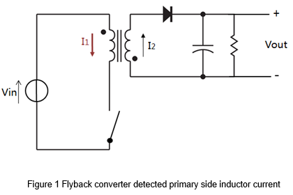
The timing of overload protection is determined by detecting the inductor current in primary side when OLP applied in a DC to DC power converter. Figure 1 shows the schematic of a Flyback converter. I1 is the primary side inductor current. Since I1 changes with the input voltage, the protection point also changes with voltage. For example, a 60W DC to DC converter will cut-off at 120% when the input is low voltage, and cut-off at 160% when the input is high voltage.
Over Current Protection (OCP)
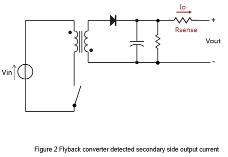
The design of overcurrent protection will detect the secondary side output current. Figure 2 shows the schematic of a Flyback converter. Io is the secondary side output current. The external current sense resistor (Rsense) used to detect Io. Due to output is a fixed voltage. The cut-off point only related to the voltage on current sense resistor. According to Ohm's law, the current sense resistor can decide the value of cut-off point, so the point does not vary with input voltage.
OCP circuit- Basic circuit
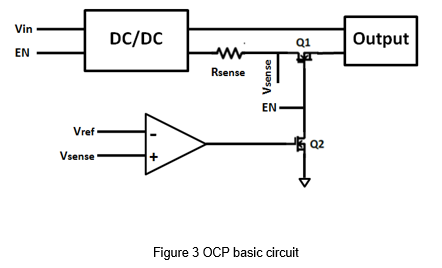
The three actions of overcurrent protection are output current detection, determine the current over standard and then cut-off. The easy way to accomplish these three actions needed a current sense resistor (Rsense), a comparator and two switching MOSFET (Q1, Q2). Figure 3 is a basic circuit schematic of OCP. The detection point of the current is the output of the secondary side. In order to compare the voltage level, the output current signal needs to convert into a voltage signal. During the normal operation, the output current is lower than the over current protection point, the comparator’s output is at logic low. So Q2 turns off, and Q1 turns on. And the dc/dc converter's output was normal. In the overload or short-circuit condition, the comparator determines that the sense voltage exceeds the reference voltage, and the comparator's output signal gets high. Q2 turns on, and Q1 turns off, so the output is disconnected.
Application-Demo board
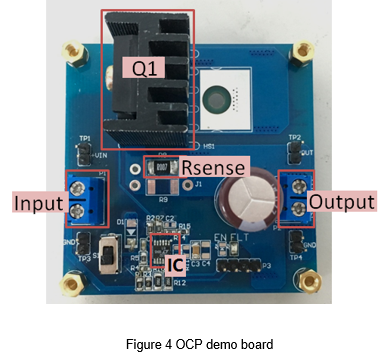
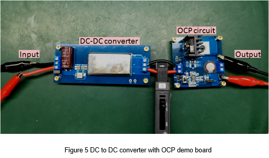
Figure 4 shows the OCP demo board, including the control IC, switching MOSFET (Q1), current sense resistor (Rsense) and other functional circuit. And the DC/ DC power converter combined with the OCP demo board, as shown in Figure 5.
Application-Function block
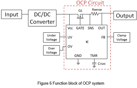
Application-IC Function
This experiment selected the LT4363 that contains a number of protection functions. The overcurrent protection is the key point of this experiment. The appropriate MOS and sense resistors can be freely selected to match the required of overcurrent protection conditions.
LT4363 has a charge pump inside to provide enough driving voltage for the n-MOSFET to turn on. It can monitor the voltage drop between the SNS and OUT pins. The internal amplifier limits the voltage across the current sense resistor to 50mV and reduces the voltage limit to 25mV during the protection mode. This means that the current must drop to half of the limit after the overcurrent occurs, and then the protection state can be released to prevent the current from continuously burdening the system.
Over Voltage Protection (OVP), Under Voltage Protection (UVP), the protection point can be set by the external resistors. When the voltage is lower than the UVP point, or the voltage is higher than the OVP point, protection will be activated and the MOS will turn off the output.
Application-Experimental condition
The following table shows the specifications of the DC to DC power converter selected for this experiment.
|
DC to DC Converter |
60W, 2x1” package |
|
Input voltage |
9~36V, Nom. 24V |
|
Output voltage |
12V |
|
Output current (full load) |
5A |
|
Efficiency (typ.) |
91% |
Application-Selection of current sense resistor
Since the detection voltage between SNS and OUT is 50mV, the selection of Rsense can be determined by the current value of the protection point. To let the converter cutoff at 150%, thus select the Rsense is 7mΩ, and calculate the over current protection point is 7.143A.
After the cutoff, the sense voltage between SNS and OUT will drop to 25mV. Calculate the release point according to Ohm's law:
As mentioned above. When the output current is lower than 3.57A, the cut-off state can be released and the normal operation can be resumed.
Application-Power loss
Since OCP is an added circuit, there is energy loss in combination with the use of a DC to DC converter. The main loss comes from MOS. The following table shows the specifications of MOS.
|
TYPE |
VDSS |
RDS(on) |
ID |
PW |
|
STW52NK25Z |
250V |
<0.045Ω |
52A |
300W |
Power losses of MOS and resistor under full load condition are:
Adding total energy loss.
According to the total loss by the above calculated, the efficiency lost by the power converter can be obtained.
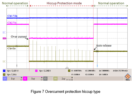
Application-Wave form
Figure 7 shows the procedure from normal operation to protection mode and auto released. When the output current reaches 7.3A, the hiccup protection is triggered. The circuit will release automatically every fixed time. If output current does not lower enough, the protection state wouldn't release. Until the output current is lower than 3.6A, the circuit will restore normal mode. C1: Input Voltage, C2: Output Voltage, C4: Output Current
Conclusion
OCP and OLP circuits are used to limit the output current to avoid overload. Under the conditions of high power converters, the OLP has more risky cause the protection point might over the safe range. Using OCP can avoid this risk but need to spend more circuit space and converter efficiency. In this article, by implementing an OCP circuit board, the multi-function IC reduces the complexity of the circuit design. IC combined with various protection functions, including overvoltage protection, overcurrent protection and undervoltage lockout. Combine with a 60W DC-DC power converter, in the end. The actual cut-off current at 146%, which is almost the same as the expected cutoff current, 150%, and the protection point is not affected by the input voltage. The function of the OCP circuit is different from the OLP. For the demand of different power products, consider the advantages and disadvantages of the two circuits, and choose the appropriate protection circuit.
CTC is a professional service provider for high-end power supply modules (AC to DC Converter and DC to DC Converter) for critical applications worldwide since 30 years. Our core competence is to design and deliver products with leading technologies, competitive pricing, extremely flexible lead-time, global technical service and high-quality manufacturing (Made In Taiwan).
CTC is the only corporation certificated with ISO-9001, IATF-16949, ISO22613(IRIS), and ESD/ANSI-2020. We can 100% ensure not only the product, but also our workflow and service to match quality management system for every high-end application from the very beginning. From design to manufacturing and technical support, every single detail is operated under highest standard.